- home
- Articles
- Difference between gate valve and valve
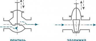
Shut-off devices used in pipeline systems have a general purpose: if necessary, they block the flow of the working medium. But each type of fittings performs this task differently. For example, gate valves and shut-off valves (valves) differ in design and functional features. Their specific advantages and disadvantages determine the choice of a specific type of reinforcement in each case. To make it easier for you to choose the right device, we will tell you about the main differences between a gate valve and a valve, the difference in their design and functionality.
Pressure, flow and level regulators
Figure 7. Pressure regulator with connecting flanges
Purpose of regulators
Regulators (reducers) of pressure, flow and level are designed to automatically maintain the corresponding parameter without the use of secondary energy sources.
Regulator design
The design of the regulator is a valve with a pneumatic or hydraulic actuator of a membrane, bellows or plunger type, as well as a special installation spring designed to adjust the regulator to the required parameter value. The designs of regulators are extremely diverse.
Level regulators are divided into:
- supply regulators, in which the level is maintained by periodically adding liquid to the vessel, and
- overflow regulators, in which excess liquid is drained.
Pressure regulator
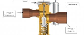
Consider a pressure regulator
using the example of a gas cylinder reducer. The opening of the gas inlet pipe is the valve seat, against which the valve plate attached to one end of the angle lever is pressed. The second end of the lever is connected to a movable membrane, which is acted on from the outside by the force of atmospheric pressure and the compression force of the installation spring, and on the other side by the force of gas pressure in the cavity of the regulator. The axis of rotation of the lever is fixed to the bottom of the regulator body. If the pressure of one of the burners of the gas stove is closed, the gas flow will decrease, as a result of which the gas pressure in the reducer cavity will begin to increase. This will cause the membrane to move, which will pull the end of the lever connected to it. The second end of the lever with the valves attached to it will also move and cover the hole for the passage of gas. As a result, the gas pressure in the reducer cavity will be at an almost constant level, since the valve stroke is extremely small and the force of the installation spring will change slightly when the membrane moves.
The regulator will ensure that the required gas flow is passed at a constant pressure value in front of the burners.
Flow regulator
Figure 7. Direct-acting flow regulator with connecting flanges.
Flow regulator is working
similar to a level regulator, maintaining a constant differential pressure across some throttling device, such as a diaphragm or adjustable nozzle. Since the local resistance coefficient of the throttling device does not change, a constant pressure drop means that the flow rate through the throttling device is constant and therefore the flow rate is constant. Some regulators have a throttle, the design of which allows you to adjust its resistance, adjusting the regulator to the required flow rate. More often, however, the resistance of the throttling device is left constant, and the compression of the set spring is changed, which allows the pressure drop across the throttle and, consequently, the flow through the regulator to be adjusted.
In regulators, an important principle is to unload the valve from the one-sided pressure of the working medium, which can significantly reduce the effort required to move the working element. The most perfect type of unloading is a double-seat valve design, when the forces acting on two plates are opposite in direction and mutually compensated. However, in this housing design it is more difficult to manufacture the housing and it is more difficult to ensure that two valves are completely sealed at the same time. Despite such difficulties, this design is very widely used in modern regulators.
This is interesting: Selection of a circulation pump for a hot water system
Mounting methods
Water valves can be connected to the process in different ways: fixed using special elements or mounted by welding.
Coupling fittings
The connecting pipe has an internal thread with a fine pitch, and the outside is shaped like a hexagon for ease of use with a wrench. The coupling is screwed onto the thread and sealed with flax strands or FUM tape.
Tsapkova
This method of fastening is characterized by the presence of an external thread at the end of the connecting pipe and a collar at the end of the pipeline.
The valve branch pipe is pressed against the pipe with its end and secured in this position using a union nut. The tightness of the connection is ensured by a metal gasket and special lubricants.
Choke
The fitting is a short piece of pipe (bushing) with internal threads at both ends. With this type of connection, the connecting ends of the fittings are screwed onto the pipe and secured with a union nut.
Ball valves characteristics and use
Ball valves are unique in their design. This is a practical modification of a plug tap. It got its name due to the fact that the cork located in its body is shaped like a ball. Ball valves are designed to control the flow of various types of fluids. Its closing and opening is carried out by turning the handle one-fourth of a turn, which achieves a significant simplification of operation when compared with other types of valves.
When the valve is in the “open” position, the ball hole is parallel to the flow line, which ensures direct flow with a low degree of friction and minimal pressure loss.
Ball valves are designed specifically for use in the oil and gas industry.
They are practical for pipelines with medium pressure and temperatures not exceeding 200 degrees. Ball valves do not require large production costs when compared with other types of valves. And the tightness when using them is also much higher.
Ball valves made of steel are considered more universal, as they have the ability to perform their function even in the presence of low temperatures and high pressures.
The following types of ball valves can be distinguished. These are valves made of brass and ball valves made of steel. Brass ball valves are successfully used in the construction industry and housing and communal services. In addition to aqueous working media, they are also suitable for low concentration glycol solutions, alcohol, gas and liquid petroleum products. Ball valves made of brass have a minimum size of 15 millimeters, a maximum of 80.
Ball valves made of steel are considered more universal, as they have the ability to perform their function even in the presence of low temperatures and high pressures. The minimum nominal diameter of a steel ball valve is the same as that of a brass valve, but the maximum reaches 500 mm.
No heating system in the modern construction industry is complete without a ball valve design. Ball valves come in both coupling, union and flange types. Ball flanged valves, or rather their design uses flanges as elements connecting the valve and the pipeline.
The obvious advantages of flanged ball valves include:
- low degree of hydraulic resistance;
- various areas of use;
- easy installation and operation.
Taps, various valves and other shut-off valves are a necessary element of any pipeline and are used in various branches of modern industry.
Add to bookmarks
They are used on pipelines with a large diameter, more than 50 mm, where it is necessary to slowly shut off the flow to prevent water hammer.
At the valve, the valve moves perpendicularly, and at the moment of closing the sealing surfaces do not experience friction, which significantly reduces the occurrence of scoring.
Due to the fact that inside the valve body the flow direction changes twice, and the flow area is smaller than that of gate valves, the valve has increased hydraulic resistance, which is its main disadvantage.
The valve cannot be operated in different directions relative to the flow. Its working position is the direction of flow when, in a closed state, it presses on the plate from the side of the seat, and not from the side of the rod. In this position, the flow pressure when the valve opens even helps lift the plate from the seat. If the valve is installed incorrectly, the flow pressure in the closed position presses the plate, and when the valve is opened, a very significant force will have to be applied to move the rod, since it will be necessary to overcome the flow pressure. This can lead to its failure, since the shutter plate can be torn off the rod, which will require large labor costs for repair.
What are locking devices made of?
Before you find out what valves are made of, you need to divide them into two types:
- installed in internal water supply networks;
- mounted on external water and gas pipelines.
If the product is intended for internal water supply networks, then devices made of brass, bronze, stainless steel and plastic are used. If the products are used for outdoor work, then the above materials are used, as well as additionally steel and cast iron.
- Plumbing fixtures made of brass and bronze are expensive options. However, their cost is justified by their quality and durability. Such devices are light in weight, small in size, and can also be installed not only on a water supply system to supply cold water, but also hot water. Such products are also used in heating systems, since scale does not settle on their surfaces.
- Stainless steel valves. Another good option that has a long service life. They are several times cheaper than brass and bronze devices.
- Plastic products are among the cheapest, but they are in no way inferior in quality to the above models. Their disadvantage is that they can only be installed in plastic pipelines.
Stainless steel devices are not recommended for installation in hot water and heating systems. After all, exposure to hot water causes the formation of scale, which subsequently reduces the diameter of the throughput channel.
Cast iron and steel valves are popular for installation on external pipelines. For the manufacture of such products, cast iron and steel are used, which will significantly reduce the price of the device. After all, similar products made of brass and bronze will cost tens of times more.
Gate valve
Gate valves are pipe fittings in which the locking part moves at right angles to the direction of movement of the medium in the pipeline. They are used primarily to completely shut off and open the flow, rarely to regulate it. The scope of their application is pipelines for various economic purposes, with a diameter from 15 mm to 2 m, with a working pressure in the system p ≤ 25 atm and T ≤ 560 °C.
The size of the valve usually corresponds to the cross-section of the pipeline. Its body has two internal seats; a shutter connected to the spindle is placed inside the body through the cover. The spindle in turn is connected to the running nut. When one of them rotates (manually by the steering wheel, or using an electric drive), the shutter moves to block/open the flow.
Advantages and disadvantages
The main difference of the valve is its low hydraulic resistance, which is especially valuable in relation to main pipelines, where low energy losses are important when pumping liquids and gases over long distances.
The disadvantages of this device include:
- significant building height (due to the retractable spindle);
- long required time for closing and opening;
- wear of sealing elements during operation;
- danger of jamming due to contamination and low operating temperatures.
According to the type of valve, there are valves
1. Wedge (the seats are located at an angle to one another, the shutter is wedge-shaped):
- wedge valve with a rigid wedge (its version is a valve with a rubberized wedge);
- double-disc (clinket valve);
- with an elastic wedge.
2. Parallel (saddles - parallel, locking discs of the shutter - too).
3. Gate valves (type with a single locking disk, including gate valves with an electric drive).
4. Hose - the flow is blocked by squeezing a flexible rubber hose with a shutter.
According to the manufacturing method and material there are
- cast (cast iron valve, aluminum, cast steel);
- steel stamped-welded.
Selection of the optimal technical solution
When choosing the optimal type of shut-off valve, the individual characteristics of the upcoming operation mode are taken into account. In addition to technical parameters, the choice of equipment is influenced by price indicators, which are especially relevant when it is necessary to purchase a large number of shut-off valves.
Application areas of valves
To complete pipelines of relatively small diameter, shut-off valves (valves) can be used, which are characterized by a simple design and low cost. The valves operate stably during pressure surges and drops in the system. Compact devices with a small building height are optimal for equipping pipeline sections running inside cramped industrial and utility rooms.
The design of the valve locking mechanism allows the use of practical fittings to complete pipelines with different characteristics of the transported medium, ensuring stable operation of process equipment. Manual control, eliminating the need for a stable power supply for the operation of the electric drive, ensures guaranteed operability of the valve in emergency situations, when the ability to quickly shut off the pipeline is especially important. The small stroke of the flywheel allows you to extremely speed up the operation of closing or opening the pipeline. The valve seal seal does not rub against the seat when moving, which has a positive effect on the period of trouble-free operation of the valve.
Features of the use of valves
When equipping pipeline networks with a diameter of more than 300 mm, it is advisable to use valves adapted for uninterrupted operation in difficult technical conditions. The short construction length of the valves allows the installation of equipment to be carried out as closely as possible, which is especially important in industrial conditions when it is necessary to rationally arrange numerous devices. Depending on the operating mode, valves with a sliding or non-retractable spindle are used, which have individual technical advantages.
Retractable spindle
Retractable spindle fittings, characterized by an increased building height, can only be installed in spacious rooms in the absence of physical restrictions. Free access to the valve running assembly ensures convenient maintenance of the equipment during operation.
The absence of negative influences from the working environment helps maintain the impeccable functionality of the running gear for convenient control and uninterrupted operation of process equipment. The main disadvantage of using valves with a rising spindle is the need to plan space for the free movement of the working unit when closing and opening the flow of the transported medium.
Non-retractable spindle
Valves equipped with a non-rising spindle are characterized by a reduced construction height, which is optimal for installing equipment in limited space. The lack of maintenance of the chassis immersed in the working environment reduces the period of maintenance-free operation of the equipment. Valves with a non-rising spindle are not recommended for use in critical facilities.
The scope of application of maintenance-free gate valves with a non-rising stem is limited to water and non-aggressive petroleum products. The working environment must be free of abrasive particles, solid impurities and corrosive properties. Compact valves are conveniently located in small rooms, technological wells, oil wells and underground communications.
Varieties
The cast iron flanged gate valve is available in various versions. Devices are divided into types according to the direction of action - parallel and perpendicular. The last option is stationary and extends perpendicular to the main flow. Parallel devices are installed with a zero angle and are not an obstacle to the flow, provided they are in standard mode.
There is also a division according to design features - these are gate, ball and wedge-shaped elements. The latter are standard type shut-off valves. They are quite effective, have a perpendicular type of blocking, but are heavy.
The ball design is similar to household locking elements of a similar type. DU 50 devices have become most widespread due to their relatively low cost. The flange valve DU 100 has a special disk element that closes the pipeline using a powerful spring. As a rule, it is installed on oil pipelines and gas networks.
Classification by control method:
- Handheld devices.
This type is controlled manually by turning a special handle or valve. Despite the need for significant physical effort, they do not require maintenance and rarely fail. - Electric drive fittings.
Has a built-in electric motor for control. The system is blocked autonomously after pressing a button.
Connecting devices to pipes
Valves are divided into two types according to the installation method:
- Coupled and threaded. The main connecting element with this connection method is the thread. It can be internal and external on the valve (popularly called “mother-father”). Fittings of this type are installed in pipelines with a pressure of no more than 1.6 MPa.
- Flanged. At the end parts of the pipes there are flanges, with the help of which cast iron or steel products are connected. Installation of such devices is carried out on main and industrial pipelines in which the water pressure exceeds 10 MPa.
Plastic valves are connected to pipelines through special welding. Knowing the features of the devices in question, you can choose the best option for the appropriate installation. Recently, ball valves have become very popular because they have a long service life, despite the inability to repair them.
The main difference between a valve and a gate valve, analysis of the design features of the design allows you to make the right choice of fittings when installing a pipeline.
Scheme of a wedge valve.
Operating principle and varieties
The operating principle of all types of valves is similar to each other. The body and cover of the valve form a cavity in which the shut-off unit is located. The body has flanges through which the valve is connected to the pipeline. Depending on the type of connection, the design can be flanged or wafer, which is clamped between the flanges of adjacent sections of the pipeline (a wafer valve has significantly smaller dimensions.
Inside the body, next to the locking element, there are two seats (parallel or at a certain angle to each other). The shutter is adjusted by rotating the actuator, to which the locking mechanism is connected via a rod. Depending on the principle of movement of the rod, the valve can be retractable (the rod performs a rotational-translational movement when closing) or rotary (exclusively rotational movement).
The rod is installed inside the running nut, this unit is called a threaded pair. The nut, when the drive rotates, ensures the movement of the locking element in a given direction. When the valve is moved to the closed position, its walls are pressed against the sealing surfaces of the seat, while in the open position the valve is completely out of the body bore.
The main classification of fittings is carried out depending on the type of locking mechanism, according to which valves are divided into:
- wedge;
- parallel;
- gate;
- hose
The valve has a conical shape; when closed, it fits into seats located at a given angle to each other and closes the passage hole. The wedge, depending on the design, can be rigid or clinket.
A rigid wedge (steel) ensures maximum tightness in the closed position, however, the operation of such a design may be accompanied by a number of problems associated with jamming of the valve due to temperature fluctuations or damage to the sealing surfaces due to corrosion.
A flanged clinker gate valve has a gate consisting of two valves placed at an angle to each other, which are rigidly connected to each other. This design is characterized by increased reliability - it does not jam, the seals are subject to minimal wear, and much less effort is required to change the position of the shutter. The flanged clinker valve is the most common type of ship fittings.
The valve consists of two disks that move between sealing seats located parallel to each other. A variation of the parallel design is, in which the locking unit has a similar design, but the shutter consists of 1 disk.
Gate valves are installed on pipelines with one-way movement of the working medium. Due to the simplicity of the design, it is not capable of ensuring maximum tightness of the ceiling, however, the gate valve is repairable, which allows the use of such structures in waste and sewer systems transporting liquid with a high content of mechanical particles.
Hose-type valves are fundamentally different from the previously discussed analogues. There are no sealing seats in their design - the working flow circulates inside an elastic rubber hose, which completely isolates the internal surfaces of the housing from the transported liquid. The flow is blocked by pinching the hose with a rod.
Such structures are intended for installation on pipelines transporting viscous substances and chemically aggressive liquids, under the influence of which accelerated corrosion of steel occurs - rubber is a material resistant to most chemical compounds. Operation of these valves is possible at temperatures up to 110 degrees
and working medium pressure up to 1.6 MPa.
This article talks about wedge flanged valves, their characteristics, operating principles, and most importantly, the use of these products on different pipelines:
Wedge flange valves are in demand in industrial communications on water, oil, and gas pipelines. They are an indispensable part of any pipeline where it is necessary to block a section or the entire pipe. These shut-off valve elements are not complex in design; they have a long service life (up to 50 years). For safe operation of the pipeline, they are installed at a certain distance from each other so that the pipe can be quickly shut off in the event of an accident or repair.
This is interesting: How to install corrugation on a toilet - useful tips
Product classification
The water valve is classified according to a number of different characteristics, which include:
- Type and design of the locking device.
- Material of manufacture.
- Features of connection with water or gas pipelines.
Based on the type and design of the locking device, valves are divided into the following types:
- Valve
- Cork or cone.
- Ball.
Let's find out the main features of each type of valve, and also determine their purpose.
Valve devices
The valve valve is also called a valve tap, since the body of the product is divided into two parts by horizontal and inclined partitions. The design of the product with an inclined partition has a hole that has a groove for the valve. This hole is called a saddle.
The valve is part of the rod, which is located at the bottom of the product. An elastic gasket is inserted into the design of the product, resting against the saddle. By means of this stop in the seat, the supply of fluid flowing through the device is blocked. At the top, the rod is equipped with a thread that connects to the threaded connection of the seat nut. Using this threaded connection, the valve is raised and lowered, thereby shutting off and regulating the pressure of the supply fluid.
Products of this type have advantages and disadvantages. The advantages include:
- Withstand high pressure.
- Adjustment of water volume and pressure.
- Easy to operate.
- If the locking device fails, it can be replaced.
The disadvantages of such a device are:
- High rate of abrasion of the gasket, since with frequent opening and closing of the device, contact of rubber with metal occurs.
- Relatively short service life.
- To completely shut off the liquid supply, you need to rotate the flywheel for a long time.
Cone type product
A cone valve is a type of valve product. The differences between the two devices lie in the design of the locking mechanism. If in the previous version the locking mechanism is presented in the form of a partition, then in this design the device has a plug in the form of a cone. When the rod rotates, the shut-off valve is lowered into the hole in the partition, thereby stopping the flow of liquid.
The advantages and disadvantages of this type of product are similar to those of a valve type valve. The cone valve has the following structure as shown below.
Ball type device
The operating principle of this type of valve is completely different from the functioning of previous options. If previous products provide shutoff of water perpendicular to the pipeline, then with a ball-type device everything is different.
The main locking device is a ball, which has a through slot proportional to the fluid flow. Shutting off the liquid supply is ensured by moving the ball with the slot to a perpendicular position. Such valves are also called gate valves.
The advantages of such products include:
- Simplicity of design, which allows the device to be used for a long time.
- Tightness of the structure. Only the shut-off ball is in contact with water, which also affects the long service life of the product.
- Shutting off and opening the liquid supply is done by turning the handle 90 degrees or half a turn. Due to the rapid shut-off of the liquid supply, such devices are also called reversible floors.
As practice shows, the quality of valve production plays a significant role in the service life. European-made water valves have a service life of up to 10 years, while cheap Chinese analogues fail after a few years.
The disadvantages of the types of valves under consideration include:
- Inability to repair a water supply ball valve. In Chinese products, the integrity of the connection between the handle and the locking ball is compromised. This causes the handle to continue to rotate and the ball to remain in place in a stuck position.
- Inability to regulate fluid flow. It is possible to regulate the flow of liquid using such a product, but in this case the manufacturers do not guarantee the long service life of the device.
Structural features
The difference between the elements lies in the design of the locking elements: for a gate valve it is a wedge, gate or parallel lock of one or two disks, which moves perpendicular to the flow, closing the passage hole; for a valve, it is a valve with a threaded spindle.
Gate valve
A valve is a part for blocking a passage opening. There are gate, hose and parallel, which is due to the design feature.
Gate valve elements:
- body made of cast iron, steel, brass,
- housing cover made of the same material as the housing,
- constipation (wedge, gate, discs),
- spindle (threaded rod) retractable or rotatable,
- flywheel or gear drive (for automatic control).
In pipelines, full bore devices are most often installed, in which the diameter of the bore is equal to the diameter of the pipe, but in some cases narrowed valves are used to reduce wear on the seals.
Valves work more efficiently on large pipelines, where the pipe diameter is above 300 mm and the pressure level is increased. The valve is devoid of bends and therefore does not create unnecessary resistance. One-sided pressure presses the valve tightly against the seat, so the device is more reliable and durable.
Valve
A shut-off device for systems for various purposes, in which the passage hole is closed using a valve.
Design elements:
- the valve body can be made of cast iron, steel, bronze;
- shut-off valve seat;
- the valve itself with a threaded spindle;
- rotation handle
A valve is used as a shut-off element, which is adjacent to the seat parallel to the movement of the working medium and divides its flow at a right angle, narrowing the passage holes. In this case, the resistance only increases, which creates additional mechanical load on the shut-off valves.
General properties
Gate valves are used as a shut-off device in sewer, water and gas pipelines.
By design, each of the elements is designed for use in systems with high pressure levels. This property is reflected in the price (valves and gate valves are more expensive than conventional valves), but nevertheless allows the devices to be used in systems where other designs would be ineffective.
Both elements are mounted to the pipe using flanges and couplings, as well as by welding, i.e. the elements can be part of either a collapsible or monolithic device.
Structurally, both designs consist of a cast body and a shut-off element for regulating the flow.
Correct installation position
Equipping various types of shut-off valves with standard steel flanges ensures simple installation operations. Flange connections allow you to quickly replace faulty shut-off valves without the need to perform complex preparatory operations. Replacement of fittings equipped with flanges is carried out without dismantling adjacent areas and carrying out welding operations. To seal connections tightened with steel studs and nuts, gaskets of the appropriate configuration are used, placed between mating flanges that are identical in size.
When installing valves, there is no need to take into account the direction of flow of the working medium. In valves, the working fluid can be transported in both directions.
Rice. 3 Gate valve sizes
When installing valves, any orientation of the device is allowed, regardless of the flow of the working medium. The design of the shut-off element of wedge and parallel valves ensures guaranteed operability of the equipment in any direction of flow of the transported liquid or gaseous medium.
How to distinguish a valve from a gate valve visually
Visually distinguishing a valve from a gate valve is difficult, but possible. To do this, you need to pay attention to the external features of the valve body, due to the movement of the shut-off unit with the specifics of the internal components.
It is much easier to understand what is in front of you, a valve or a valve, by reading the markings on the body. All types of shut-off valves have a digital designation. For gate valves it is 30, 31, and for valves it is 13, 14, 15.
If the housing has “14” at the beginning of the designation, then this is a valve. The marking also includes data on the presence/absence of a drive, housing material, etc.
Functional Features
Both devices are designed to block the flow of the transported working medium in the pipes, with the only difference being that the valve is capable of limiting and completely blocking the movement, and the valve can only be in two positions: either closed, when the movement stops, or open, when the flow circulates freely.
Conclusions website
- The valve has two positions - the “open” position and the “closed” position.
- The design of the valve, in addition to turning it on/off, also allows you to regulate the pressure of the working flow.
- Visually, a faucet differs from a valve in the following way: if the handle is simple and its end is attached to the stem, it is a faucet; if there is a “wing” on the stem instead of a handle, it is a valve.
Add site to bookmarks
- Kinds
- Choice
- Installation
- Finishing
- Repair
- Installation
- Device
- Cleaning
Advantages and disadvantages of valves
Valve design diagram: 1 - valve body, 2 - nut, 3 - washer, 4 - gasket, 5 - valve, 6 - seal, 7 - rod, 8 - special bushing, 9, 16 - oil seal, 10, 15 - oil seal bushing, 11 - flywheel, 12 - washer, 13 - screw, 14 - cap washer.
The main advantage of valves is that there is no need to overcome the pressure of the medium during the movement of the working element, which in turn is the force required to move the valve. Of considerable importance is the direct flow of the transported medium and the low resistance coefficient in the open state.
Due to the symmetry of the design, it is possible to use valves in different directions of movement of the transported medium, without unnecessary assembly and disassembly of flange connections when it is necessary to change the direction of movement of the internal medium.
The main disadvantage of the design is that in the process of moving the working body of the valves, strong friction occurs. Gate valves have a large construction height due to the need to extend the stem.
When the valve is located in an intermediate position, the seat section is partially blocked by the plates, the flow actively flows around the lower areas of the sealing ring surfaces, exposing them to abrasive wear by solid inclusions of the working medium. Therefore, after operation in partial closing mode, the valves do not provide sufficient tightness when they are closed. This drawback is inherent in various types of fittings and limits the use of the valve as a control element. In addition, the control characteristics of the valves are unsatisfactory.
Comparison
The main difference between a valve and a faucet is that a valve can regulate the pressure of the working flow, but a faucet cannot (besides, adjustment with a faucet is strictly prohibited according to the operating rules). The tap performs only two functions, having only the “open” or “closed” position, and the valve can easily regulate the pressure of the working flow.
It's all about the design differences between the valve and the tap. In valves, the shut-off element sits on a seat, moving in the direction of flow, and in taps it turns around its own axis. In addition, valves are usually ball valves, that is, when the ball is turned, the diameter of the hole changes, and the valves are equipped with a main axle box (by unscrewing or twisting the rod of the main axle box, they raise or lower the valve attached to the rod, thereby opening or closing the hole located in saddle).
Design and functions of valves
Scheme of a gate valve device: 1-gate, 2-guide plate, 3-seat, 4-body, 5-ring, 6-rod, 7-pack of seals, 8-flywheel, 9-pointer, 10-bearing housing, 11- cover, 12-oiler, 13-ring.
A valve is a valve whose shutter is moved by a threaded pair.
The structures are manufactured in a threaded (coupling) design and for connection to pipe flanges.
Depending on the relative position of the outlet and inlet connecting pipes, angle and straight valves are separated. The category of through passages includes structures in which the axes of the outlet and inlet connecting pipes are parallel or coincide. The angle valve, in turn, is equipped with mutually perpendicular axes.
Depending on their purpose, they are divided into shut-off, safety, regulating, shut-off, bypass, breathing, and return.
The valve can be single-seated or double-seated. Single-seat valves, in turn, are divided into needle and disc valves based on the shape of the valve. A manually operated valve in which the valve is moved by a threaded pair is often called a gate valve. There are control and shut-off valves. The purpose of shut-off valves is to completely block the flow of the medium; for this purpose they are equipped with a shut-off device.
Membrane valves are fitting structures in which the flow of a medium is blocked using an elastically deformable membrane (plastic, rubber). These systems are made of cast iron with an internal coating of corrosion-resistant materials (rubber, plastic, enamel).
A hose valve is a fitting design in which the flow of a medium is blocked by pinching a rubber hose located inside the valve. Valves with both one-way and two-way hose clamping are used.
The breathing valve is designed to release accumulated air or vapors and prevent the formation of a vacuum in the tanks during the process of “big” and “small” breathing. The concept of “large” breathing occurs with the flow and flow of fluid, “small” breathing is caused by temperature fluctuations.
Thanks to check valves, it is possible to prevent the formation of a reverse flow of media. In check valves, the shut-off element is opened by a direct flow of medium and closed by a reverse flow. Lifting check valve design has a shutter that performs a reciprocating movement. Structures equipped with a mesh are installed at the beginning of the suction pipeline. A swing check valve has a gate that rotates about a horizontal axis that is located above the center of the valve seat.
Valves: main characteristics
Mandatory components of the design of a direct-acting safety valve are a shut-off element and a setpoint.
Unlike a gate valve, this valve is equipped with a cone or flat plate-shaped gate, which makes reciprocating movements along the surface of the seat.
Valves are divided into safety, breathing, bypass shut-off, control, check valves, etc. They come in single- and double-seat types. According to the shape of the shutter, single-seat ones are disc-shaped and needle-shaped. A manually operated valve with a threaded shutter movement is called a valve. Valve fittings are divided into shut-off and control valves.
Shut-off valves, or valves, completely shut off the flow. They are always single seated.
There are also diaphragm valves. These are structures that block the flow with an elastic membrane made of plastic or rubber. Such valves usually have a cast iron body with internal cavities coated with an anti-corrosion layer (enamel, plastic or rubber).
Control valves are designed for analogue regulation of medium flow and are equipped with a single- or double-seat control element.
Valve
The difference between a valve and a gate valve is that its shut-off element (disc-shaped (spool-shaped), needle-shaped) moves parallel to the flow of substance in the pipe. A shut-off valve (correctly a valve) is also used primarily to block the movement of a medium in a pipe, but can also be used to regulate hydraulic resistance in a pipeline (flow intensity).
Shut-off valves provide better sealing when blocking the flow, therefore they are used in much more difficult conditions (pressure in the system from full vacuum to 250 atm, temperature range from –200 to +600 °C). But you have to pay for this in size - valves are used only on pipes with a relatively small cross-section (DN 15–150). On pipes of larger diameter, the force of pressure of the flow of substance on a parallel-moving spool significantly complicates its control.
The design of the valve is significantly different - it consists of a body with an internal seat, which is closed by a slide valve. The spool is driven by a rotary spindle moving along the running nut of the yoke assembly. The spindle is rotated by a manual steering wheel or an electric drive motor.
Depending on the nature of connecting the pipes to the pipeline network, there are: flanged, coupling, and union valves. According to the manufacturing method and material, they are usually cast (cast iron flanged valve, made of aluminum, brass alloys) or stamped-welded steel.
The direct-flow valve, also known as a balancing valve, is somewhat different in design. In its body, the flow is maximally straightened to minimize hydraulic resistance. It is locked by a spool on a spindle inclined relative to the axis of the pipeline. It is most suitable for regulating hydraulic resistance (current intensity).
The flow of liquid or gas in the body of a straight-through shut-off valve, as a rule, makes two turns of 90 degrees, which causes its relatively high hydraulic resistance. It limits its use on pipelines in favor of shorter distribution pipeline networks, pipeline systems of machines and assemblies.
The valves have the following advantages
- short spindle stroke when the shutter is fully closed;
- better conditions for ensuring tightness of flow shutoff;
- minimal wear by friction of seals.
Significant disadvantages include:
- high hydraulic resistance, which significantly increases energy consumption for pumping the medium, and the required pressure in the pipeline;
- limited bore diameter, which does not allow their use on large cross-section pipelines (more than 15 cm);
- the presence of stagnant zones in which pollution accumulates.
According to economic importance, they differ:
- water valve (water valve);
- distribution network gas valve;
- valve for a gas cylinder, etc.
Shut-off valves are an important part of pipeline fittings
In everyday life, people use water and gas that come through pipes every day. It is very important for us that the flow of liquid or gas flows freely or is stopped in a timely manner. Shut-off valves, in particular, shut-off valves, are used for this purpose. Often the operation of many large enterprises depends on the serviceability of valves - water utilities, heating networks, oil refineries, chemical plants, gas pipelines. There are different types of valves - direct and reverse shut-off valves, safety valves, control valves, which can be automatic or controlled either manually or electrically.
Shut-off valves help us stop the flow of any liquid or gas by turning the valve. With the help of safety valves, excess air or water can be drained from the system (which is especially important for systems where the flow moves under pressure), and a check valve prevents liquid or gas from moving in the opposite direction.
The straight shut-off valve is traditionally used in two-pipe water heating systems, where copper or stainless steel pipes are provided. Using the valve, you can turn off an individual heating device and dismantle it without draining water from the entire system.
A sealless diaphragm type water shut-off valve is usually installed on water pipes. Such valves are leak-tight because they are made in the form of a flask and are not equipped with external seals that wear out. Its peculiarity is that it does not affect the throughput, since it operates from zero pressure.
Shut-off valves are most often used for small-diameter pipelines, since at high pressures greater effort is required to control them. This is perhaps their only drawback. Also, unlike gate valves, valves have “dead” areas where rust or other solids can accumulate, which can lead to corrosion.
By design, shut-off valves differ from gate valves in that the flow movement coincides with the movement of the gate. The small valve stroke, as well as the minimum building height, have made the valves much more popular. Shut-off valves are also highly resistant to high pressure and temperatures. They can be used in aggressive environments.
Shut-off valves today for various needs and depending on the pipe material used can be made of steel, brass, bronze, glass, plastic, porcelain, titanium.
Design features depend on the location of application of the shut-off valves. For example, an angle valve is installed at pipeline turns, and a straight-through and direct-flow valve is installed on horizontal or vertical sections of pipes. In this case, the arrow on the product body always strictly corresponds to the direction of flow.
The variety of nuances in the design allows the use of shut-off valves in many areas. So, they are equipped with pumps, compressors, even internal combustion engines.
fb.ru
Design differences
You can often come across the phrase “valve valve”. But in fact, there is a difference between a gate valve and a valve in the design and operating principle of the shut-off element. Thus, in a valve, in most cases, the lumen of the pipeline is blocked by a wedge, which moves perpendicular to the flow of the working medium. And at the valve, the shutter is made in the form of a cone or disk (spool) moving parallel to the flow. When closing the valve, the shutter moves against the flow of the medium; when opening, it moves vice versa.
In order for any pipeline shut-off mechanism to work, an appropriate structure of the valve body is necessary. The valve has a cylindrical body, the medium moves straight through it. When the device is open, the flow may be slightly obstructed by the narrowing of the lumen and the presence of o-rings in it (they ensure a tight fit of the wedge when the valve is closed). This design is characterized by low hydraulic resistance.
The valve body is much more complex. In it, the flow of the medium makes two successive turns at right angles. This creates a lot of resistance when the valve is raised and significantly reduces the flow rate. But when closing and opening a shut-off valve, the shutter moves only 0.25 DN, and for gate valves it must be moved to the full diameter. Because of this, the valves have a much higher construction height.
Briefly the main design features of the valve and gate valve are given in the table:
| Constructive | Gate valve | Valve |
| Hull structure | The body is simple cylindrical (full bore or narrowed), the medium flow moves straight | Housing with a complex internal design, thanks to which the flow turns 90° twice |
| Gate | Wedge, gate | Spool, cone-shaped valve |
| Direction of movement of the locking element | Perpendicular to flow | Parallel to the flow |
| Types of connections to the pipeline | Flanged, socket, welded | |
| Control methods | Manual (flywheel), using a mechanical gearbox, drive mechanisms (force is transmitted to the valve through a threaded pair) | |
Functional differences: advantages and disadvantages
How does a gate valve differ from a valve in terms of operation? Let's start with the fact that these two types of fittings have a lot in common:
- Variety of material designs. This allows you to select a gate valve or valve for any working environment.
- Both gate valves and shut-off valves are available with different methods of connection to the pipeline. They are convenient to install into the system.
- Both types of devices provide high tightness of the overlap. They are used only to completely shut off the flow and cannot serve as control valves (except for special models).
At the same time, valves and valves have their pros and cons. For clarity, we have collected them in a table:
| Gate valve | Valve |
| – Large valve stroke for full opening (1 nominal diameter), therefore, it takes a long time to open and close the valve | + Small valve stroke for full opening (up to 0.25 nominal diameter), so the valve can be opened or closed faster than a gate valve |
| + Low hydraulic resistance (for full bore valves it is practically absent) | – High hydraulic resistance due to complex housing design |
| + Absence of stagnant zones, which allows the use of valves with thick, viscous, contaminated media | – The presence of stagnant zones in the design of the shut-off valve limits its scope of application, since with some media this feature can cause accelerated corrosion |
| – It is more difficult to ensure high tightness of the overlap during the manufacture of fittings | + It is easier to ensure the required tightness of the valve |
| – Friction when closing and opening the valve gradually leads to wear of the sealing surfaces of the wedge and body | + There is virtually no friction when the bolt is seated |
| – To seal the valves with respect to the external environment, seals are used | + Gland or bellows seal possible |
| – Valves are installed only on straight sections of the pipeline | + There are straight-through and angle shut-off valves. Angled ones can be installed in places where pipelines turn 90° |
| – The direction of movement of the medium during installation does not matter | + During installation, the fittings should be installed so that the arrow on the body coincides with the direction of the medium flow |
| + Possibility of using valves on pipelines with large diameters. Above 30mm in diameter they work more efficiently than valves | – Diameter limitation (with a large nominal diameter, the operation of the valve becomes much more complicated; a powerful flow of medium prevents the valve from properly seating in the seat) |
| – Large construction height and weight | + Low construction height, less weight than a gate valve |
| + Short face-to-face length | – Face-to-face length is approximately 1.5 times greater than that of a valve of similar DN |
Thus, there are fundamental differences between a valve and a gate valve that affect the scope of their application and the process of operation.
Temperature conditions
The range of permissible temperatures during operation of shut-off valves depends on the material of the housing of the internal components. Steel valves and various modifications of steel gate valves are capable of functioning reliably at high temperatures of the transported medium, reaching several hundred degrees. The use of heat-resistant components that are not subject to corrosion ensures a high level of tightness when transporting cold water, steam, oil products and process fluids. The carbon steel spindle has high strength and consistent functionality when operating in different temperature conditions.
Inexpensive cast iron valve models are optimized for controlling the flow of working fluid with temperatures up to +90 °C. Cast iron valves can be used to equip water supply, fire, heating and sewer networks. The fittings for large-diameter pipelines are equipped with a gear mechanism that simplifies the operations of closing and opening the shut-off unit. The use of high-strength polymer seals ensures guaranteed tightness of blocking the flow, regardless of temperature indicators.
Designation
A valve is a device that is placed on gas, air, water, steam, oil and other pipe lines to close and open passage holes using a valve. The valve consists of a steel, cast iron or bronze body containing a valve seat, the valve itself with a screw-threaded spindle and a handle that allows the spindle to rotate.
Valves are connected to the pipeline using threads or flanges and are divided into coupling and flange valves.
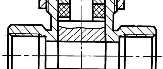
Sectional view of valve
A valve is a device that is placed on a pipe line to close and open passage holes using a valve that moves perpendicular to the axis of the flow of the working medium. Depending on the design of the shut-off element, valves are divided into hose, gate and parallel.
The spindles can be retractable or rotatable.
Gate valve in section to contents ^