July 17, 2021 kmelectric equipment and faults
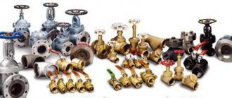
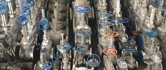
The term “valve” itself is quite common among ordinary people. Indeed, when they say “valve”, it is immediately clear what we are talking about - a tap that needs to be turned for the water to flow/stop. The term “valve” is less common in everyday life. It is mistakenly assumed that we are talking about some kind of vibrating partition, like in the human heart. In fact, “shut-off valve” and “shut-off valve” are the same thing! We are talking about shut-off valves, which allow you to control the distribution of the medium through the pipeline. On the website https://al-safa.kz/zadvizhki/chugunnye/ you can purchase cast iron valves at the best prices.
Many professionals (especially those of the old school) still call the above structures valves. However, starting from the eighties of the last century, technical instructions prescribe the use of the term “valve”.
Advantages and disadvantages [edit | edit code ]
In addition to the above advantages, valves also have others, for example:
- possibility of use in conditions of high temperatures and pressures, vacuum, corrosive and aggressive environments;
- comparative ease of maintenance and repair under operating conditions.
The design of valves is in many ways similar to the design of gate valves, but its fundamental difference is that the movement of the gate coincides with the axis of movement of the medium flow, and not perpendicular to it, giving valves a number of advantages over gate valves, including:
- small stroke of the valve for full opening (usually no more than 0.25 of the nominal diameter, while for gate valves - no less than the diameter) and, accordingly, low construction height and weight;
- in valves it is much easier than in gate valves to ensure the required tightness of the valve (by using o-rings made of various non-metallic materials);
- when closing and opening the valve, unlike a gate valve, friction between the valve
and
the seat
, which significantly reduces wear of the sealing surfaces; - the possibility of using a bellows as a seal for fittings in relation to the external environment.
The disadvantages of valves include:
- high (compared to ball valves and gate valves) hydraulic resistance, which, with large passage diameters and high fluid velocities, creates large energy losses and necessitates a corresponding increase in the initial pressure in the system;
- limitation of application limits by diameter, which was mentioned above;
- the presence in most structures of stagnant zones in which mechanical impurities from the working environment and sludge accumulate, which leads to the intensification of corrosion processes in the valve body [4][5].
Application area
Needle valves are not as popular as ball and balance valves and should not be confused with them.
Main Applications:
- Placement on auxiliary pipelines with pressure up to 10 MPa (with the exception of high-pressure taps) to control the flow of liquid, steam, and gases. The conical plunger head is more reliable than the straight seats of classic valves. This prevents scuffing of the sealing rings.
- Pipelines with increased medium pressure. Needle rods allow you to regulate the flow without interrupting the operation of the system.
- For connecting pressure gauges;
- In cooling water injection systems;
- In heating for air release;
- In carburetors of cars and motorcycles (in the form of a needle valve);
- When making moonshine. Here, needle valves are used to control the rate of release of the membrane (or any other) reflux condenser product from the distillation cube into the cooling system.
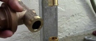
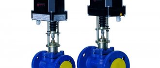
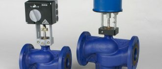
Design and principle of operation [edit | edit code ]
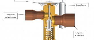
Frame (4)
(yellow in the explanatory figure) has two pipes with ends for connection to the pipeline; it can be by any known method: flange, coupling, fitting, pin, welding.
Inside the body there is a seat, which in the “closed” position is closed by a shutter (spool (3)
).
The spindle (1)
passes through the gland seal in the cover.
In the design shown in the explanatory figure, the running gear of the shut-off body is moved outside the working environment area using a yoke assembly (2)
. The seal can also be a bellows seal; in this case, removal of the running unit is not required.
Differences in designs [ edit | edit code ]
Seal designs [ edit | edit code ]
According to the method of sealing the movable connection between the spindle (stem) and the cover, valves are divided into stuffing box
,
bellows
and
membrane
(diaphragm).
Stuffing box fittings [ edit | edit code ]
In stuffing box fittings, the tightness of the connection between the cover and the moving part of the valve is ensured by a stuffing box device. The essence of the stuffing box device is that on the outside of the cover or body, in the place where the rod or spindle passes through it, a stuffing box is created into which sealing material is placed - stuffing box packing. Using special devices, the packing is pressed along the axis of the spindle (rod), resting against the walls of the stuffing box and compacted. This creates a tight seal and the working environment does not penetrate outside the housing. In fittings of small diameters, the packing is compressed with a union nut, in larger diameters - with a special part - an oil seal using two folding or anchor bolts with nuts.
The gland seal has many advantages that make it preferable in most cases. Among them:
- the ability to manufacture stuffing box packings from various materials to ensure good sealing over a wide range of operating pressures and temperatures;
- simplicity of design;
- possibility of re-stuffing the oil seal or changing the packing during operation.
Oil seals simplify the design as much as possible and reduce the cost of the fittings, however, for a nominal pressure of 2.5 MPa and a nominal diameter of more than 50 (these limits are very approximate), the running unit is removed from the working environment area and is located above the stuffing box, and the running nut is placed in the yoke unit, located above the valve cover, that is, the design becomes significantly more complicated to eliminate the influence of the working environment on the spindle-nut connection and increase its durability and reliability.
Bellows fittings [ edit | edit code ]
In bellows fittings, the seal of moving elements relative to the external environment is ensured by a bellows assembly. Its main element is a bellows - a corrugated tube. The metal bellows is connected by welding or soldering to the upper or lower rings (or other shaped parts), forming a so-called bellows assembly. The bellows assembly, with its upper part, is motionlessly and hermetically connected to the body parts of the valve, and the lower part is connected to the valve stem or spool, thus blocking the possibility of the working medium escaping to the outside. The forward movement of the rod to control the spool occurs inside the bellows, which can change its length due to the deformation of the corrugations.
Bellows valves are used to operate in environments where leakage into the environment is unacceptable. The advantage of such valves over stuffing box valves is the elimination of leakage of the working medium into the atmosphere within the service life of the bellows assembly. But this advantage is achieved by significantly complicating the design and, accordingly, increasing the cost of the valve. In addition, repairing a valve bellows due to fatigue failure is a complex operation to replace the bellows assembly, so in such cases the valve must be replaced with a new one.
Membrane fittings [ edit | edit code ]
Diaphragm valves are fundamentally different from valves of other designs.
In membrane fittings, external sealing is provided by a membrane made in the form of an elastic disk made of elastic materials (rubber, fluoroplastic). The profile of the membrane allows in its central part to carry out a reciprocating movement sufficient to close or open the shut-off or control valve of the valve. The membrane is installed and clamped along the outer diameter between the body and the cover, this ensures the tightness of the connection of the body parts and at the same time completely cuts off the internal cavity of the valve from the external environment [6] .
The peculiarity of these valves is that the diaphragm can simultaneously act as a shutter, blocking the passage of the working medium through the body under the action of the spindle.
This design allows, without the use of stainless steel, to have cast iron valves suitable for various aggressive environments. This is achieved by coating (lining) the internal surfaces of the housing with various corrosion-resistant materials (fluoroplastic, rubber, polyethylene, enamels).
The disadvantages of such valves are the short service life of the membrane and the limits of their use limited by low pressures and temperatures [4].
Functional Features
Both devices are designed to block the flow of the transported working medium in the pipes, with the only difference being that the valve is capable of limiting and completely blocking the movement, and the valve can only be in two positions: either closed, when the movement stops, or open, when the flow circulates freely.
Differences
The devices in question perform an almost identical task, but have several differences. Let's take the following points as an example:
- Gates serve to shut off flow, but can also be used for temporary adjustment. Manufacturers do not recommend using valves as a control mechanism.
- Valves are almost never used to regulate flow, due to design features. Such a device is used exclusively to block the flow.
- Valves primarily perform a control function. But there are also devices on sale that block the flow.
The valve and gates are adjusted manually or from a remote control unit. But many valves operate in automatic mode; the design is activated in certain situations. In addition, valves often have a more compact design.
Varieties
The cast iron flanged gate valve is available in various versions. Devices are divided into types according to the direction of action - parallel and perpendicular. The last option is stationary and extends perpendicular to the main flow. Parallel devices are installed with a zero angle and are not an obstacle to the flow, provided they are in standard mode.
There is also a division according to design features - these are gate, ball and wedge-shaped elements. The latter are standard type shut-off valves. They are quite effective, have a perpendicular type of blocking, but are heavy.
The ball design is similar to household locking elements of a similar type. DU 50 devices have become most widespread due to their relatively low cost. The flange valve DU 100 has a special disk element that closes the pipeline using a powerful spring. As a rule, it is installed on oil pipelines and gas networks.
Classification by control method:
- Handheld devices.
This type is controlled manually by turning a special handle or valve. Despite the need for significant physical effort, they do not require maintenance and rarely fail. - Electric drive fittings.
Has a built-in electric motor for control. The system is blocked autonomously after pressing a button.
What is a shutter
The shutter is a special mechanism designed to regulate the pressure force or completely close it. A similar device is used for large pipeline diameters. The most widespread are disc valves. Their peculiarity lies in the following points:
- The structural element that prevents the flow is made in the form of a disk, the diameter of which corresponds to the diameter of the cross section.
- The opening or closing of the locking element is carried out by rotating around an axis. In this case, the structural element is connected directly to the handle, but the force can also be transmitted through a special device that simplifies turning the handle under strong pressure.
- The design features determine that it cannot be used with high pressure in the system.
What is the difference between a valve and a faucet?
The significant difference between these two types of pipe fittings is that the valve is designed to regulate the flow of a moving substance. The tap is capable of operating only in the “open/closed” mode ; it does not provide intermediate options for the position of the locking body. Using it to regulate movement will lead to rapid wear.
The valve valve has a disc-shaped closing element, like a valve, and is also designed to regulate the flow.
Classification of the valves under consideration
There are quite a large number of different shutters. The differences are as follows:
- The shutter can be a flat disk or in the form of lens surfaces.
- Classification is also carried out according to the type of material used in manufacturing. The most common models are made of cast iron or stainless steel.
- The interior of some structures can be lined with rubber liners.
The control design is similar to that used when creating ball valves. Some models have a gearbox or flywheel that can increase the force applied to the handle.
In addition, the main classification lies in the diametrical size of the passage hole.
Tips for choosing
Before purchasing, please pay attention to the following points:
- Scope of the element. Choose a product with appropriate technical characteristics;
- Material of manufacture (cast iron, steel, bronze, stainless steel). Usually the best option in terms of price-quality ratio is cast iron or inexpensive stainless steel. If you plan to operate in aggressive environments, choose bronze and stainless steel with a high nickel content (grade AISI304 or 12×18n9);
- If you choose a device for regulating high-pressure flows, carbon steel (grade U8, U10, etc.) is suitable;
- Pay attention to the quality of the part - when closing, the needle should not touch the support, and when opening, it should not come out of the socket;
- Choose your connection type wisely. It can be coupling or flanged;
- For centralized heating systems, it is better to use a Mayevsky manual tap, which allows you to bleed off the air accumulated in the radiators at any convenient time. For private homes, an automatic option is suitable. An automatic faucet is also suitable for use in places with difficult access.
You can find many reviews of needle taps on the Internet that can help you with your choice. But almost all of them are described in our article.
What is a valve
A valve is a structure that is capable of blocking the flow by moving the control element perpendicular to the pipeline. This type of control element is very popular. The complexity of the design lies in converting rotation into reciprocating motion. Most shut-off elements are designed for systems with a maximum pressure of 25 MPa, the temperature can reach a temperature of 565 degrees Celsius.
The scope of application of valves is as follows:
- Water and gas supply system.
- Housing and communal services systems.
- Oil pipelines.
The design has quite a lot of advantages:
- Small construction length.
- Relatively simple design.
- There is little resistance that is created in the open position.
- Can be used in a wide variety of systems.
The point is that when open, the passage hole of the locking mechanism does not create additional resistance. Therefore, most often the valve is installed in a system in which the flow moves at high speed.
Valves also have disadvantages:
- Significant time required to open and close the structure.
- Large construction height. As a rule, the height of the valve is more than twice the diametrical size.
- The presence of sealing elements that wear out quickly. But significant problems arise with repairs.
It is worth considering that the scope of application of valves is exclusively to close the system. They do not serve to regulate the flow of the medium, since a high flow rate causes deformation of the locking plate.
conclusions
Check valves are applicable in pipelines of any industries and housing and communal services.
- Installed on horizontal and vertical pipelines.
- They are connected using the following methods: welding, flange and wafer.
- Controlled automatically or manually.
- The design is simple and effective, with a small number of parts.
- They are light in weight and dimensions
In November 2021 Our company took part in the annual congress on petrochemicals and oil refining PRC Russia&CIS. More than 200 representatives from Russia and the CIS gathered in Moscow to discuss pressing issues of industry development. At the thematic exhibition, we demonstrated our new design development - a butterfly valve with triple eccentricity APA.3X. Taking into account the needs of the market, our specialists have created a unique…
A flanged strainer is a must-have component for transport pipelines and for many process pipe systems. It is intended: for cleaning liquid and gaseous technological media in closed heating, cooling, preheating systems; for primary mechanical filtration of natural waters from wells, artesian springs, rivers, lakes and ponds, ensuring primary purification before supplying water to high-tech treatment plants...
A shut-off and control valve is a pipeline system fitting designed to regulate the flow of working fluid until the supply is completely shut off. Such devices operate in water supply, gas and radiator heating networks. Valves or flaps (a more modern name), due to the simplicity and reliability of their design, are widely used in all areas of economics, industry and everyday life. They are used to work with both…
A liquid check valve refers to devices that prevent the return movement of liquids in pipelines. The fittings reduce internal pressure, eliminating leakage or stopping the working pump. This type of valve is intended for use in public utilities, water and heat supply, as well as in the chemical, oil, and food industries. Types and types of check valves Disc check valve. The product is easy to install and inexpensive. Principle…
Shut-off devices used in pipeline systems have a general purpose: if necessary, they block the flow of the working medium. But each type of fittings performs this task differently. For example, gate valves and shut-off valves (valves) differ in design and functional features. Their specific advantages and disadvantages determine the choice of a specific type of reinforcement in each case. To make it easier for you to choose the right device, we will tell you about the main differences between a gate valve and a valve, the difference in their design and functionality.
Valves classification
The main feature of the classification is the type of locking mechanism. Based on this criterion, we distinguish the following types of design:
- Wedge valves.
- Hard wedge.
- Double disc wedge.
- Elastic valve.
- Parallel valve.
- Gate valve.
- Hose type valve.
Each variety has its own advantages and disadvantages that should be taken into account.
What is a valve
The valve, unlike previous types of design, is designed to regulate the flow force rather than block it. Their design may differ significantly. The most common types of valves are:
A check valve is very common in water supply systems. It is needed in order to relieve excess pressure in the system. As for the control valve, they can be installed to set the required flow rate. In addition, there are also shut-off and control devices that can not only control the flow rate, but also shut it off.