Hello, dear reader! In industrial pipelines, through which a huge flow of liquids continuously moves, it is necessary to regulate this movement by reducing or increasing the flow speed and pressure in the pipes. In such cases, an indispensable role is played by a shut-off control valve with an electric drive. In our article we will look at its types and characteristics, connection methods, rules of use, and get acquainted with the advice of specialists on installing and operating the unit.
What is it and what is it for?
A shut-off valve with various types of drives is a device with which you can completely or partially block the moving flow of liquid in a pipeline.
The peculiarity of the electric drive design is that it allows these actions to be performed remotely, almost anywhere on the highway.
Purpose and scope of application
Control valves allow you to automatically control at a distance the process of regulating fluid flow and pressure in pipelines.
They are used in large trunk, technological and utility network channels through which the environment is transported.
Electric drive devices can be either shut-off devices, with the function of only completely blocking the pipe, or with the function of regulating the flow force by completely or partially stopping it.
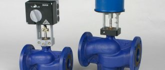
Rotary control valves for steam and gas with electric drive
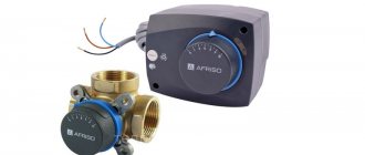
The range includes a control valve with a Danfoss electric drive , represented by two- and three-way models (the electric gear drive is purchased separately), and single- and double-seat shut-off and control valves with a Broen electric drive. Valves are used at central and individual heating points, supply ventilation systems of greenhouses, in water supply systems and other areas of the economy as a shut-off device or to automate the regulation of technological processes. The calculation of the control valve for steam is carried out in accordance with regulatory documents. The valves are used with electric actuators, thermostats, pneumatic actuators, and differential pressure regulators, which you can purchase separately. Here you will find components for installation and ensuring smooth operation of the valves.
Controls and technical characteristics
The valve is controlled by the linear movement of the rod with the plunger. The device is started by pressing the start button on the remote control. Under the influence of electric current, the drive transmits force to the plunger. It, moving up and down, changes the cross-sectional area of the passage hole.
The main technical characteristics of shut-off control valves are:
- the value of the nominal pressure in the system that the device can withstand;
- nominal diameter size in mm;
- conditional throughput in m3/h;
- temperature limits at which the unit operates normally;
- network voltage intended for the electric drive.
Duct fire damper
A duct valve with the possibility of connecting an air duct on at least one side consists of a rectangular or round body, a damper and an electric drive.
The valve is structurally comparable to a section of air duct. The body of the rectangular valve with two connecting flanges is made of carbon or galvanized steel. Round duct valves are made of galvanized steel and can have two options for connecting to round ducts: flange or nipple. The box-type damper is made of galvanized steel and filled from the inside with fire-resistant heat-insulating material. Cases and dampers are made from stainless steel upon request. The valves have a fixed size range of working sections corresponding to the generally accepted size range of channel equipment. Fire-prevention normally open (fire-retarding) valves KLOP-1 are designed to block the spread of fire and combustion products through air ducts, shafts and channels of ventilation and air conditioning systems of buildings and structures for various purposes. Normally closed valves KLOP-1 are used as valves for mechanical supply and exhaust smoke ventilation; the valves can also be used as smoke valves. The valves are used in accordance with regulatory requirements. KLOP-1 valves cannot be installed in rooms of categories A and B due to fire and explosion hazard. In these premises, explosion-proof valves KLOP-1 or KLOP-2 are installed.
Fire resistance limit of KLOP®-1 valves (60/90)
– in normally open (fire-retarding) valve mode:
when the drive is located on the thermal side - EI 60/90;
when the drive is located on the side opposite to the thermal effect - EI 60/90; when installing the valve on a section of the air duct outside the enclosing
building structure with a standardized fire resistance limit - EI 60/90;
– in normally closed valve mode – EI 60/90;
– in smoke valve mode – E 60/90.
In accordance with the entry in the NO certificates, KLOP®-1(60/90) valves can be installed both in a fire-resistant building structure (fire barrier) and outside it in the section of a fire-resistant air duct, regardless of the direction of the possible thermal effect on their structure. In accordance with the requirement of clause 6.11 of SP 7.13130.2013, this allows the installation of valves on any side of the fire barrier, regardless of the location of the fire in relation to this barrier. Compliance with the requirement of clause 6.11 is ensured by the presence of a casing that protects the drive of NO valves both when they are installed in a fire-resistant building structure, and when the valves are installed on a section of the air duct outside this structure.
KLOP-1 valves are produced with a rectangular cross-section only of the “channel” type with two flanges. The valve drive is installed outside the housing. The valve body is made of carbon cold-rolled steel and then painted. On special order, the housing can be made of stainless steel. The body and damper of such valves are made of stainless steel (Spanish: “Stainless Steel”), the remaining components and structural elements are made of carbon steel with anti-corrosion zinc coating. The valve flaps are filled with thermal insulation.
Normally open (NO) valves KLOP®-1 are manufactured in various modifications depending on the type of actuator:
– with an electromagnetic drive in combination with a thermal lock at 72°C (on special order at 93 or 141°C);
– with BELIMO electromechanical actuators type BFL, BFN, BLF or BF (for large valves) in combination with a thermal release device at 72°C (on special order at 93 or 141°C);
Normally closed (NC) valves KLOP-1 are produced with an electromagnetic actuator without a thermal lock or reversible BELIMO actuators of the BLE or BE type (for large valves).
KLOP-1 valves are operational in any spatial orientation. When designing and installing valves in ventilation systems, it is recommended to take into account ease of access to the valve drive and inspection hatches in its body. When installing KLOP-1 valves in large cross-section air ducts in areas located behind a sharp change in the direction of air flow, for example, behind 90° bends, it is recommended to ensure that the valve damper is in an open position in the plane of flow rotation or to use KLOP-3 valves. The climatic version of the valves is U3 according to GOST 15150-69. The valves can be installed in enclosed spaces with air temperatures from -30°C to +40°C, where fluctuations in temperature and air humidity are significantly less than outside the building. The environment must be explosion-proof, not containing aggressive vapors and gases in concentrations that destroy metals, paint and varnish coatings and electrical insulation.
Valve overhang values for rectangular valve body
| B, mm | 150 | 200 | 250 | 300 | 350 | 400 | 450 | 500 | 550 | 600 | 650 | 700 | 750 | 800 | 850 | 900 | 950 | 1000 | |
| X, | mm | 0 | 0 | 22 | 47 | 72 | 97 | 122 | 147 | 172 | 197 | 222 | 247 | 272 | 297 | 322 | 347 | 372 | 397 |
| X1, | mm | 0 | 0 | 0 | 0 | 0 | 0 | 0 | 0 | 12 | 37 | 62 | 87 | 112 | 137 | 162 | 187 | 212 | 237 |
X, X1 - damper overhang beyond the damper body, mm
To compensate for the length of damper overhang (for example, when installing a decorative grille on a flange or when installing the damper in a building structure thicker than L1), additional sections of the air duct of the appropriate length can be manufactured
Valves for maritime climates and damp areas
Valves for areas with a maritime climate are made of stainless steel. The electromechanical or reversible BELIMO actuator is housed in an enclosure with a protection degree of IP 66. The valve body is made of rectangular cross-section.
Normally open valves with an electromechanical drive are manufactured without hydraulic valves (including explosion-proof valves).
The fire resistance limit of the valve is A 60 (60 min).
Type of climatic modification - OM2 according to GOST 15150-69. Characteristics of the external environment during valve operation:
maximum operating values of ambient air temperature: upper value – plus 45°C; lower – minus 30°С;
the average monthly relative humidity in the warmest and most humid period is 70% at 22°C;
the upper value of relative air humidity is -98% at 25°C; atmosphere type – III according to GOST 15150-69.
The valves of the “marine” design have passed tests for compliance with the requirements for valves for exposure to salt fog, splash resistance and dust resistance, based on the results of which a corresponding conclusion was obtained. The valves have a certificate of type approval from the Russian Maritime Register of Shipping and a certificate of approval from the Russian River Register, which allows them to be used both on sea vessels and stationary offshore platforms, and on river vessels. These valves can be installed in rooms with high humidity.
Transport valves
The valves have design features that take into account the specific operating conditions at transport facilities and can be used in ventilation and air conditioning systems for railway rolling stock. The valves have been tested for vibration and impact resistance.
Valves for rooms with increased requirements for cleanliness of the working environment
Valves are manufactured in rectangular and circular cross-sections. The body and damper of such valves are made of stainless steel, the remaining components and structural elements are made of carbon steel with anti-corrosion zinc coating. In the designation structure of these valves in the project specification and when ordering, the design option (stainless steel) must be additionally indicated in parentheses. The valves are used in the pharmaceutical, microelectronics industries, etc.
The main technical characteristics of special-purpose valves are similar to the characteristics of KLOP-1 valves of conventional (general industrial) design.
FIRE-PROOF EXPLOSION-PROOF VALVES BUG 1
The valves are certified for compliance with the “Technical Regulations on Fire Safety Requirements” and the Technical Regulations of the Customs Union “On the Safety of Equipment for Operation in Explosive Environments”
Explosion-proof valves can be installed in premises of categories A and B in terms of explosion and fire hazard, in explosive zones of classes B-1, V-1a, V-1b and V-1g according to the PUE classification, where, according to operating conditions, it is possible:
- formation of explosive mixtures of gases and vapors with air belonging to categories IIA, IIB and IIC according to GOST 30852.11-2002 or GOST R IEC 60079-20-1-2011 at a maximum surface temperature according to temperature classes T1, T2, T3, T4, T5, T6 according to GOST 30852.5-2002 or GOST R IEC 60079-20-1-2011;
- formation of layers of combustible dust and explosive dust-air mixtures belonging to categories IIIA, IIIB and IIIC according to GOST R IEC 60079-0-2011, GOST IEC 61241-3-2011.
Ex-marking of explosion protection for explosive gas atmospheres:
– drive I Ex d IIC T6 Gb according to GOST R IEC 60079-0-2011;
– valve II Gb according to GOST 31441.1-2011 (EN 13463-1:2001).
Ex-marking for protection against ignition of combustible dust:
– drive Ex tb IIIC T850C according to GOST IEC 61241-0-2011;
– III Db valve according to GOST 31441.1-2011 (EN 13463-1:2001).
Degree of protection of the drive from external influences according to GOST 14254-96: IP 66.
The explosion-proof valve can be installed in explosive zones 1 and 2 according to the classification GOST 31610.10-2012, as well as in zones class 21 and 22 according to GOST IEC 61241-3-2011 in accordance with the explosion protection marking. In this case, the environment may contain explosive conductive volatile particles and dust in accordance with the explosion protection marking.
The need and possibility of installing an explosion-proof valve in a specific potentially explosive area can be determined in accordance with Chapter 7.3. PUE, as well as according to GOST 31610.10-2012 and GOST IEC 61241-1-2-2011. The design of the explosion-proof shell is made taking into account the requirements of GOST R IEC 60079-1-2011.
KLOP-1 with BELIMO electric drive in an explosion-proof enclosure
Fire resistance limit of KLOP®-1(60/90) valves:
– in normally open (fire-retarding) valve mode:
when the drive is located on the thermal side - EI 60 /90;
when the drive is located on the side opposite to the thermal effect - EI 60 /90;
when installing the valve on a section of the air duct outside the building envelope with a standardized fire resistance limit - EI 60/90;
– in normally closed valve mode – EI 60 /90;
– in smoke valve mode – E 60 /90.
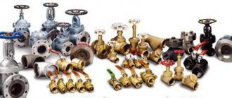
Connection type
According to the type of connection, shut-off and control devices are divided into
- flanged,
- fittings,
- coupling,
- pin,
- welded
The first option is the most preferable. As a rule, valves of this type are already equipped with flanges. They are used in networks with high pressure. Through the flange, the unit can be attached to any pipes of suitable nominal diameter. It also does not depend on what type of device will be connected.
The welded connection method is not recommended when installing a return mechanism, removable models and valves. It is used only for steel units.
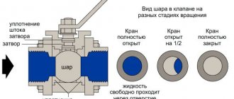
Device
The simplest control valve consists of a body with flanges, in which there is a seat, a rod with a plunger at the end and a sealing unit responsible for sealing all shut-off valves.
When the plunger closes only part of the passage opening, the water flow in the system decreases. A plunger tightly lowered into the seat blocks the flow, the pressure in the pipe after the fittings drops to zero.
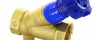
If ball valves are used in household pipelines, then in industrial pipelines and utility networks preference is given to spool valves and valves with an electric motor.
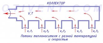
Purpose
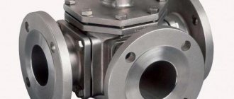
There are 2, 3, 4-way control (separating, mixing) valves. A two-way valve has one inlet and one outlet and is a shut-off valve. Flow control valves include 3 and 4 way valves. They have, respectively, one hole for the entrance and several for the exit. By blocking some of them with a valve, you can regulate the intensity of the output flow.
The two-way valve is the simplest of the devices. It can operate in the following modes:
- completely close the feed;
- rated power - the valve is fully open to a predetermined flow rate;
- intermediate power - the valve is set to pass from 10% to half the flow of the rated power.
The motorized gas valve opening mechanism stretches and retains the return spring. As soon as the power supply is interrupted, this spring returns the damper to the "closed" position.
Note! The installation of an electric valve with the mechanism of action described above is mandatory for fire ventilation systems (GOST RF 53301 for a fire shut-off valve).
In fire protection systems, certification is impossible without installing similar electric shut-off valves on ventilation lines. Thanks to their automatic operation, the supply of oxygen to the room is stopped, which inhibits the combustion process.
In heating and water supply transport mains, the installation of such fittings is not mandatory. However, its use greatly simplifies and speeds up the processes of adjusting the intensity of flows and pressure in the system.
Principle of operation
The operating principle of a motorized valve is very similar to that of a conventional valve. They are distinguished by their control method and functionality.
Based on the principle of operation, there are devices that block, mix or divide the main flow.
Shut-off units include two-way saddle valves, which are widely used in municipal heating networks.
For mixing and dividing the flow, three-way options are used, having three pipes for connection to the main line.
Types and differences of designs
According to the drive design, valves are divided into controlled ones:
- manually;
- electric drives;
- pneumatic drives;
- electromagnetic way.
According to the locking mechanism, structures are divided into:
- shut-off valves, designed only to shut off the medium;
- membrane, with a rubber membrane in the housing, adapted for operation in gas networks;
- reverse, closing when the flow direction changes;
- spool valve, which regulates the flow intensity by moving the movable spool;
- saddle type, with linear movement of a rod with a plunger, closing or opening the flow path with the help of saddles.
Advantages and disadvantages
The advantages of a pneumatic drive are its affordable price; devices with such controls are cheaper than their electric counterparts.
Valves with an electromagnetic drive greatly facilitate the process of remote control of the environment over a long section of the pipeline and allow the implementation of an electronic control system.
The device itself will be able to take accurate indicators of the condition of the same coolant in pipelines, transmit to the operator information about the pressure level, the amount of liquid in the flow, and even reset the positions of the shut-off parts of the structure.
However, the price and complexity of the devices will increase.
Tips for choosing
The optimal choice of device should ensure high accuracy in regulation. It is necessary to take into account many factors in order to make the right decision on purchasing a unit.
It is important to contact an experienced and market-proven supplier with a well-deserved reputation.
When selecting fittings, pay attention to:
- product labeling, which indicates the throughput and nominal pressure for the device;
- maintenance conditions for the device, whether it can be repaired without removing it from the line;
- is it possible to change the throughput of the device;
- the presence of structural elements in the device that reduce noise.
Principles for choosing an electric drive
If you want to select an electric drive yourself, you should consider several main aspects of these devices.
- Drive mount type.
Joining can be done in different ways. The most common types of fastening are latches, nuts and cups. So, when choosing a valve, you must take into account the type of connection to the electric drive. - Type of valve action.
The valves also differ in their operating principle. They are geared and thermoelectric. The operation of gear drives occurs thanks to a gear transmission. This type of device allows energy to be transferred from the motor itself directly to the valve, which powers it. The thermoelectric type of drives operates on an electric spiral. The coil itself heats up and increases the pressure. As it rises, the valve stem begins its work. - Stock size.
This operating parameter can vary from 5 to 50 mm. It is important to know that for correct operation it is necessary to select a drive whose stroke value will exceed the rod value. - Performance.
This indicator seems unimportant, but it is worth paying attention to it. So, there are fast and slow electric drives. Thus, it is preferable to install a fast type of device on inertial systems (average reaction speed is 3 seconds). - Voltage.
It is especially worth considering the voltage level, which can vary from 24 to the usual 220 V. - Working effort.
It is also worth taking into account and focusing on this parameter almost in the first place. So, it can vary from 50 to 5000 N. - Protection.
An important parameter is the presence of additional devices. The most important of them are protective. Typically, a high-quality device is equipped with a spring, which ensures quick closing without electricity. The device may also have an additional air damper. Its function is to protect the heater from low temperatures.
Taking these parameters into account when choosing an electric drive, you can have complete confidence in the correct operation of the device.
If the choice of electric drive raises any questions for you, you can contact Ventar-S specialists to clarify all the aspects that interest you. Our consultants will give the necessary recommendations and help in making the right choice.
Rules for installation and operation of the device
Before installing the device, check the fasteners, the inside of the valve and the main pipes to identify and remove foreign particles. If the need arises, the device is washed and purged.
After installation, check the device for functionality.
During operation, it is necessary to periodically, at least twice a year, inspect the device and carry out routine maintenance.
Check the general condition of the device and its fasteners.
All work on the solenoid valve must be carried out in accordance with the instructions supplied with it.
Required tools and materials
You will need the following set of tools:
screwdriver with appropriate attachments;
- screwdriver;
- pliers;
- flushing hose.
Materials:
- set of bolts;
- copper tubes for wires;
- electrical wire
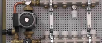
Connection diagram
Classic two-way control valve installation diagram
Work progress
When installing flanges, make sure that there are no distortions. Do not use excessive force when eliminating misalignment, otherwise the flanges of the device body may be deformed.
During installation, strictly ensure that the arrow on the housing coincides with the direction of flow.
After installation, the device is opened, thoroughly washed and blown.
Check the sealing of the connections and the rod sealing unit.
The functionality of the device is checked by connecting to the electrical network. The valve must operate at full stroke five times without supplying medium. All parts should move easily and without jerking.
What types of electric drives are there?
Today, manufacturers can offer a wide selection of electric ventilation drives
. So, if necessary, you can purchase electric drives of the following types:
- For smoke exhaust valves;
- For dampers;
- For special purposes;
- For fire dampers;
- For control valves.
Important: Ventar-S guarantees the quality of the products presented in the catalog. All products have been certified and meet the requirements of all international standards.
Frequent errors and problems during installation
Purchase of a product with an increased nominal bore (DN). Throughput higher than normal will negatively affect the accuracy of regulation.
If you select a valve with a reduced nominal bore, it will not be able to provide the required steam flow at the set pressure. This will lead to the fact that the pressure and temperature of the medium in the pipe after the shut-off device will become lower than the values necessary for the normal functioning of the heating network.
Failure to comply with technology when installing fittings.
These errors can cause instability in the operation of the control system and lead to malfunction of the valve and electric actuator.
Compression fittings
Compression fittings are designed for installation of water supply systems , mainly for connecting metal, metal-plastic or copper pipes. The presence of a crimp ring allows installation without the use of welding or threading tools. At the same time, the products are highly resistant to pressure and vibration. Fittings can be made of various materials.
The simplicity of the fitting design ensures ease of connection and reliability in operation. The most popular fittings are made from an alloy of brass and copper, treated with nickel for greater strength and durability. If you require coupling fittings, plugs, tees and other crimp-type fittings, then in the Santekhkomplekt catalog you will select the necessary parts. We offer a full range of components for the installation of pipeline systems.
Expert advice
In steam pipelines, a condensate trap must be installed in front of the control valves to ensure timely removal of condensate.
During installation, welding should not be carried out on the pipeline with the valve installed, so as not to damage the seals.
The pipeline can be protected from the undesirable consequences of water hammer by a system of check valves, in which the locking element is a steel disk. They are installed using flanged connections at certain intervals, which allows them to effectively withstand water hammer.