Uneven heating of heating system elements is the most common problem in many multi-storey and private buildings. The reasons for this phenomenon may be incorrect selection or installation of equipment, insufficient amount of coolant in the system, and so on. To solve the problem with the least amount of money and time, an automatic or manual balancing valve is installed.
Equipment for adjusting the operation of the heating system
What is this device? What criteria are used to select a valve? What should you consider when installing and adjusting equipment? The answers follow.
Device and principle of operation
The main operating elements of a valve intended for balancing are:
- body, in most cases made of various metals and their alloys. The housing is equipped with threaded pipes of different sizes intended for fixing equipment;
- a spindle designed to reduce/increase the coolant flow;
- control systems;
- O-rings;
- fittings for measuring coolant flow in the system.
Internal structure of the balancing valve
The operating principle of the valve is as follows. If there are malfunctions in the operation of the heating system and uneven heating of component elements is detected, system parameters are measured and the coolant flow is increased by opening the control valves.
Conversely, if one section of the system heats up excessively, the valve closes, reducing throughput.
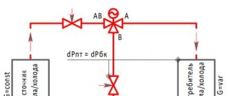
Operating principle of the balancing valve
Why is it needed?
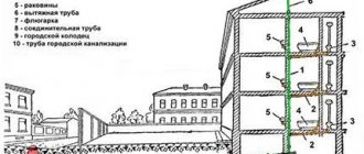
Modern large heating systems are not able to cope with the uneven movement of warm water, which leads to improper heating in different rooms. Often, incorrect calculation of water supply leads to the fact that the coolant consumption is very high, and not all the liquid reaches the radiators in the back room.
To equalize the flow of warm water supplied by boilers in different branches of the heating system, balancing valves are used, which ensure high-quality operation of the coolants.
The purpose of the product can be different - it is used both in the hot water pipeline and in heating systems for residential premises of various types and sizes, including if electric heat pumps are installed in the pipeline.
Most often, this device is used by specialists in hydraulic systems to regulate the local level of hydraulic resistance by reducing or increasing the cross-section inside the mechanism. It is simple in design and, thanks to its mechanical operation, can function smoothly. Once we have figured out what it is, we can proceed to selecting the product and installing it.
Balancing valve selection
To choose the right valve for your heating system, you must consider:
- type of equipment;
- technical specifications;
- installation method;
- manufacturing company.
Varieties
Depending on the control method, there are:
- manual;
- automatic.
The manual setting is done by the user independently by rotating the handle that opens/closes the flow of coolant.
With manual control method
The manual valve is different:
- stable operation at constant pressure in the heating system;
- ease of control;
- low cost.
The manual balancing valve is preferably installed in systems with a small number of connected radiators and where there is sufficient free space for control.
Equipment operating in automatic mode allows you to achieve uniform adjustment of the system.
An automatic valve, in contrast to manually controlled equipment, helps to simultaneously control several heating radiators connected to the same line.
With autonomous control method
The advantages of equipment operating in automatic mode are the following aspects:
- quick response to changes in heating system parameters;
- the ability to maintain constant pressure, which eliminates the possibility of hydraulic shocks leading to leaks;
- the ability to create zones with special conditions, for example, for growing seedlings.
Among the negative factors are:
- high cost;
- the need to install additional equipment in heating systems - thermostats.
You can also classify balancing valves:
- according to the engineering system. There are combined and specific. Specific valves can be used in pipelines for any purpose (heating, water supply, etc.) only if the appropriate model is selected. Combined ones are universal;
- according to the type of locking device. Valves and ball mechanisms are manufactured. The shut-off and balancing valve allows for more precise adjustment of the system, unlike a ball valve. However, when using a coolant in the form of a thick liquid, it is advisable to use ball mechanisms.
Determination of technical parameters
At the next stage, the device is selected according to technical parameters. Of significant importance are:
- Maximum temperature;
- operating and peak pressure in the system;
- through hole (Dn);
- conditional capacity Kvy, determined taking into account the correction factor Kvs, set to 1.3;
- dimensions;
- type and size of thread.
The parameters of the balancing valve indicated in the accompanying documentation must fully correspond to the similar parameters of the heating system.
Accompanying documentation indicating equipment parameters
Choosing a mounting method
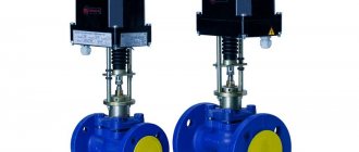
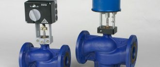
Depending on the installation method, the thermostatic balancing valve can be:
- threaded (figures above), that is, the equipment is connected to the pipes using threads. The most common option for household systems, characterized by relatively low cost, ease of installation and use.
The threaded connection is reusable and, if necessary, the equipment can be replaced or repaired in the shortest possible time. However, when installing the device using a threaded method, it is recommended to use additional means for sealing (FUM tape, Tangit Unilok thread, and so on);
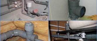
- flanged Mainly used in the construction of industrial pipelines and highways. The flange connection method is simple and tight;
Equipment fixed with flanges
- welded Installation by welding can be carried out both in domestic and industrial conditions. The fastening is the most reliable and airtight. However, installation requires special equipment and minimal skills to work with it. In addition, the resulting connection is permanent and in the event of a malfunction, a full range of replacement work will be required.
Equipment installed by welding
Popular manufacturers
When choosing, special attention is paid to the selection of the manufacturer, since the reliability and service life of the fittings depend on this parameter.
Experts prefer valves manufactured by the following companies:
- Danfoss (Denmark). The company produces high-quality equipment of various types. Particularly in demand are automatic valves of the Danfoss ASV series (equipment intended for heat and water supply systems) and AB-RM (universal devices), as well as a manually operated model of the Leno™ MSV-BD series, combining the capabilities of a balancing valve and a ball valve;
Balancing valves from the Danish company Danfoss
- Cimberio (Italy). Valves of the CIM series are available in different diameters and with different technical parameters. All equipment is complemented by high-strength sealing gaskets, allowing to achieve the maximum level of tightness;
- Broen (Denmark). Manually operated valves of the BALLOREX Venturi series are made on the basis of ball valves and can be used for any type of coolant.
You can also pay attention to the Italian company Valtec, the Swedish company TOUR ANDERSSON, which produces products under the STAD brand, and the Comap company from France.
How to balance a radiator network
Typically, installers of heating systems set the coolant flow rate on the batteries in a simple way: they divide the number of revolutions of the balancing valve by the number of heating devices and in this way calculate the adjustment step. Moving from the last radiator to the first, close the taps with the resulting difference in speed.
Example. On one “arm” of the dead-end system we have 5 radiators with Oventrop manual valves with 4.5 spindle turns. Divide 4.5 by 5, we get an adjustment step of about 0.9 turns. This means that we open the penultimate heating device by 3.6 turns, the third by 2.7, the second by 1.8, and the first by 0.9 turns.
The method is quite approximate and does not take into account the different power of batteries, and therefore can be used as a preliminary setting with adjustments during operation.
A contact thermometer that measures the surface temperature of pipes and radiators will help you balance your heating more accurately.
Our experienced expert Vladimir Sukhorukov offers another technique based on measuring the actual surface temperature of heaters. The step-by-step balancing instructions look like this:
- Open all balancing valves as much as possible and put the system into operating mode with a supply temperature of 80 °C.
- Use a contact thermometer to measure the temperature of all heating devices.
- Eliminate the resulting difference by tightening the taps of the first and middle radiators; do not touch the end ones. Open the near battery by 1-1.5 turns of the valve, the middle ones by 2-2.5.
- Allow the system to adapt to the new settings for 20 minutes and repeat the measurements. Your task is to achieve a minimum temperature difference between the battery farthest and closest to the boiler.
Note. The weather and outside temperature do not matter, only the difference in the heating of the radiators is important. By the way, in normal operating mode at 50-70 °C at the supply temperature delta will become even lower. How the system is hydraulically balanced using balancing valves, watch the video from an expert:
What is the difference between a tap and a valve?
A standard balancing valve for regulating fluid flow is a cheap analogue of the original valve, which allows you to regulate the flow area more smoothly and accurately. Also, the second one has holes in its design for measuring the amount of liquid passed by a flow meter.
The valve is essentially a simpler balancing valve, since it also serves to regulate the resistance of the passing liquid, but it does not have holes for measuring the amount of heated liquid material.
Another product that controls coolant flow is balancing valves. It works on the same principle as standard valves, although there are models with holes for measurements. The ability to take measurements is an important indicator for the correct installation of such devices, so when choosing products, focus on those that have holes in their design for this.
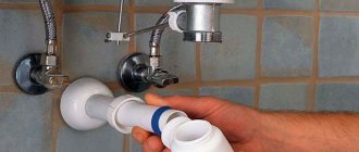
DIY installation
Installation in a hot water supply system or heating system is only possible if the device is provided for by its design and there are problems with the distribution of liquids.
You can install the unit yourself, the main thing is to take into account the installation rules and certain features of the work. You need to have water supply or heating piping diagrams on hand.
Operating principle and design
The balancing valve design is similar to that of a conventional ball valve, but it has distinctive details:
- Shutter indicator;
- Measuring diaphragm;
- The pipe on which the faucet is installed;
- Position lock.
The body is usually made of brass or steel. Also, for proper functioning, a membrane in the form of a seal is installed in the structure. The seat and valve monitor fluid flow. The designer also contains a valve stem; it comes in four types: straight, oblique, rising or falling. To understand how this device works, you can see the figure below.
As can be seen in the image, the rod has an oblique shape, which reduces hydraulic resistance. Such a unit has high precision control of liquid flow by differential pressure regulators and excellent performance in terms of service life despite the coolant temperature.
Installation Rules
- In order to avoid turbulence inside the circuits, the product must be installed on a straight section of the pipe;
- Observe the direction of flow of hot liquid, it is indicated on the body of the product; the same rule is appropriate if an additional check valve is installed;
- Before installation, be sure to flush the heating pipeline and drain all liquid from it;
- After installation has been completed, the balancing valve must be adjusted to allow the device to function correctly in the future;
- During installation, monitor the position of the spindle and other structural parts; they must comply with the standard;