Three-way valve with servo drive ESBE
I open the veil of secrets about the operation of the servo drive for three-way valves.
I provide passport data and a video of the servo drive working. I also show how to connect and mount and then configure the servomotor for a three-way valve.
And so let's get started.
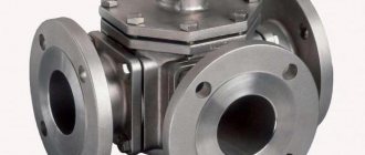
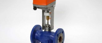
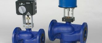
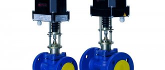
In this article we will look at the most versatile servo drive today, ESBE 99K2, which is shown in the picture, and the ESBE VRG131 valve.
The servomotor is sold with two connection kits, for two different standards of three-way valves with a circular rotating valve for unlimited rotation. More details will be indicated both in the passport and in the video.
1. The three-way valve itself contains a ball valve that rotates in a circular direction for unlimited rotation. For work, the valve must be turned clockwise and counterclockwise from 90-180 degrees of rotation.
2. Servo is the electrical equipment and device to rotate this ball valve. By rotating the valve, two passages are opened and closed, and the third passage is constantly open. The servo drive, through a temperature sensor, rotates in the desired direction to open or close the hot circulation line. More details in the video and in the passport. We also look at how to configure the valve for a specific circuit.
Servo drive ESBE 99K2, advantages:
| Power supply 220 Volt Electric remote temperature sensor Temperature adjustment (15-70 degrees) in real time Time adjustment (1-70 seconds) for checking the temperature sensor and turning on the rotation. Rotation adjustment: from 10-180 degrees Switching rotation clockwise and counterclockwise (reverse) |
At 90 degrees, it is possible to set the required rotation of the ball valve in real time for testing (press the button and scroll). If a 180 degree rotation is required, the handle is not installed and adjustment cannot be made. And this is of no use, the function is only useful for masters when testing the mixing unit.
Flaw:
If there is no power, the valve does not return to any position, but freezes in the position in which it was set automatically.
In general, it is used for large facilities where it is necessary to make a mixing unit with a high flow rate (from 2 cubic meters per hour and above).
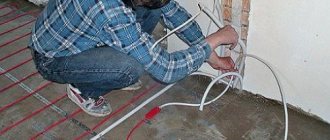
Connection
Servo setup
To constantly maintain a comfortable thermal balance in the house, an element such as a three-way valve on the heating system is included in the heating circuit, which evenly distributes heat throughout all rooms.
Despite the importance of this unit, it does not have a complex design. Let's look at the design features and operating principles of a three-way valve. What rules should you follow when choosing a device and what nuances are present in its installation.
Features of Three Way Valve
The water entering the radiator has a certain temperature, which is often not possible to influence. The three-way valve makes adjustments by changing not the temperature, but the amount of liquid.
This makes it possible, without changing the area of the radiator, to supply the rooms with the required amount of heat, but only within the limits of the system’s power.
Separating and mixing devices
Visually, a three-way valve is similar to a tee, but performs completely different functions. Such a unit, equipped with a thermostat, belongs to the shut-off valves and is one of its main elements.
There are two types of these devices: separation and mixing.
The first ones are used when the coolant needs to be supplied simultaneously in several directions. In fact, the unit is a mixer that forms a stable flow at a set temperature. It is installed in a network through which heated air is supplied, and in water supply systems.
Products of the second type are used to combine flows and their thermoregulation. There are two openings for incoming flows having different temperatures, and one for their exit. They are used when installing heated floors to prevent overheating of the surface.
The three-way valve and temperature controller are sold separately. For autonomous heating systems, purchasing a design with a thermostat is still considered a more rational and effective solution.
Design of three-way valves
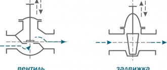
According to their design, valves are divided into seat valves and rotary valves. The principle of operation of the former is based on the rhythmic movement of the rod vertically - the “rod-seat” adjustment scheme. This type belongs to mixing type valves. Often control is carried out by an electromechanical drive.
The key element of the rotary design is the rotating sector. During movement, the rod acts on the ball valve, and it partially or completely cuts off the coolant supply. This adjustment scheme is called “ball-socket”.
These devices have increased wear resistance. They are adapted to large temperature differences and are classified as shut-off valves. In private homes, where water is consumed in relatively small quantities, they can also function as faucets.
A special feature of the mixing valve is the presence of one outlet and two inlets. It is designed to control the temperature of the working fluid by combining high and low temperature flows. With proper installation, the product can also separate flows.
A three-way dividing valve is used when it is necessary to supply hot coolant in several directions.
All models of such cranes differ from each other in certain ways:
- mechanics of the shutter - it can be either tension or stuffing box;
- plug shape - there are L, T, S-shaped;
- type of shutter - cylindrical, spherical, conical;
- connection to the circuit - using a coupling, flange, welding, etc.;
- control method - automatic, semi-automatic, manual.
The mixing device is equipped with a rod located in the center, and there is only one ball valve in it. It closes the inlet valve at the right moment.
Where are three-way valves used?
Valves of this type are found in different designs. They are included in the installation diagram of underfloor heating to ensure uniform heating of all its sections and to prevent overheating of individual branches.
If there is a solid fuel boiler, condensation is often observed in its chamber. Installing a three-way tap will help combat it.
A three-way device works effectively in a heating system when there is a need to connect the DHW circuit and separate the heat flows.
The use of a valve in radiator piping allows you to do without a bypass. Installing it on the return line creates the conditions for installing a short circuit.
Nuances of choosing a device
The following guidelines are general when selecting a suitable three-way valve:
- Reputable manufacturers are preferred. Often on the market you can find low-quality shut-off valves from unknown companies.
- Copper or brass products have greater wear resistance.
- Manual control is more reliable, but less functional.
The key point is the technical parameters of the system in which it is supposed to be installed. The following characteristics are taken into account: pressure level, the highest temperature of the coolant at the point of installation of the device, the permissible pressure drop, the volume of water passing through the valve.
Only a valve with the correct capacity will work well. To do this, you need to compare the performance of your plumbing system with the throughput coefficient of the device. It is mandatory indicated on each model.
For rooms of limited space, such as a bathroom, it is irrational to choose an expensive valve with a thermomixer.
Large areas with heated floors require a device with automatic temperature control. The guideline for selection should also be the product’s compliance with GOST 12894-2005 .
The cost can be very different, it all depends on the manufacturer.
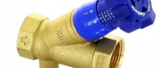
In country houses with a solid fuel boiler installed, the heating circuit is not very complicated. A three-way valve of a simplified design is quite suitable here.
It operates autonomously and does not have a thermal head, sensor, or even a rod. The thermostatic element that controls its operation is set to a specific temperature and is located in the housing.
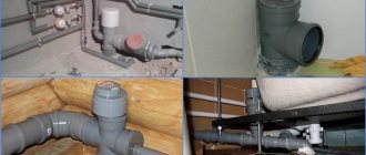
Product installation features
During the installation of three-way valves, many nuances arise. The smooth functioning of the heating system depends on their accounting. The manufacturer includes instructions for each valve, compliance with which will help you avoid many troubles later.
General installation recommendations
The main thing is to initially install the valve in the correct position, following the tips indicated by the arrows on the body. Signs indicate the trajectory of the water flow.
The symbol A indicates direct travel, B - perpendicular or bypass direction, AB - combined input or output.
Based on the direction, there are two valve models:
- with a symmetrical or T-shaped design;
- with asymmetrical or L-shaped.
When installed along the first of them, liquid enters the valve through the end holes. It comes out through the central one after mixing.
In the second option, the warm flow enters from the end, and the cold flow enters from below. The exit after mixing the liquid of different temperatures occurs through the second end.
The second important point when installing a mixing valve is that its drive or thermostatic head must not be positioned downward. Before starting work, preparation is necessary: turn off the water before the installation point. Next, check the pipeline for the presence of residues in it that could cause failure of the valve gasket.
The main thing is to choose a place for installation so that the valve can be accessed. It may have to be checked or dismantled in the future. All this requires free space.
Mixing valve insert
When installing a three-way mixing valve into a district heating system, there may be several options. The choice of circuit depends on the nature of the heating system connection.
When, according to the operating conditions of the boiler, such a phenomenon as overheating of the coolant in the return is permissible, excess pressure necessarily arises. In this case, a jumper is installed that throttles the excess pressure. It is installed parallel to the valve mixture.
The diagram in the photo is a guarantee of high-quality regulation of system parameters. If the three-way valve is connected directly to the boiler, which is most often the case in autonomous heating systems, a balancing valve must be inserted.
If you neglect the recommendation regarding the installation of a balancing device, significant changes in the flow rate of the working fluid, depending on the position of the rod, may occur in port AB.
Connection according to the above diagram does not guarantee the absence of coolant circulation through the source. To achieve this, you need to additionally connect a hydraulic limiter and a circulation pump to its circuit.
The mixing valve is also installed for the purpose of separating flows. The need for this arises when it is unacceptable to completely isolate the source circuit, but bypassing the liquid to the return is possible. Most often, this option is used when there is an autonomous boiler room.
Please be aware that some models may cause vibration and noise. This occurs due to inconsistency in the flow directions in the pipeline and the mixing product. Because of this, the pressure at the valve may drop below the permissible level.
Installation of separating device
When the source temperature is higher than the consumer needs, a valve is included in the circuit that separates the flows. In this case, with a constant flow rate both in the boiler circuit and by the consumer, superheated liquid will not reach the latter.
For the circuit to work, a pump must be present in both circuits.
Based on the above, general recommendations can be summarized:
- When installing any three-way valve, pressure gauges are installed before and after it.
- To avoid the entry of all sorts of impurities, a filter is installed in front of the product.
- The device body must not be subjected to any loads.
- Good regulation must be ensured by inserting devices in front of the valve that throttle excess pressure.
- When installed, the valve must not be above the actuator.
It is also necessary to maintain straight sections before and after the product recommended by the manufacturer. Failure to comply with this rule will result in a change in the declared technical characteristics. The warranty on the device will not apply.
How to install a dividing valve with your own hands
Providing quantitative regulation by changing fluid flow rates is the main function performed by such a three-way valve. Its operating principle is extremely simple and was discussed above. It is used where it is possible to bypass liquid to the “return”, but stopping circulation, on the contrary, is not allowed.
Note! This connection scheme has gained wide popularity in water and air heating units that are connected from individual boiler houses.
In order to link hydraulic circuits, it is necessary that the consumer's pressure losses be equal to the losses at the balancer valve in the bypass. The diagram presented here is intended for installation on those pipelines in which there is excessive pressure. In this case, the liquid moves due to the strong pressure generated by a circulation pump.
Conclusions and useful video on the topic
Installation nuances, taking into account which guarantees proper operation of the valve:
Details of valve installation when installing heated floors:
A component in the heating system such as a thermostatic three-way valve is necessary, but not in all cases. Its presence is a guarantee of rational use of the coolant, allowing for economical fuel consumption. Additionally, it also acts as a device that ensures the safe operation of the TT boiler.
However, before purchasing such a device, you must first consult about the feasibility of its installation.
If you have the necessary experience or knowledge on the topic of the article and you can share it with visitors to our site, please leave your comments and ask questions in the block below.
Three way valve for heating
At the outlet of the boiler installation, the coolant has a certain temperature, which is automatically maintained within the user-specified value. But often several circuits of the heating system require water at different temperatures, which cannot be provided by boiler automation. In this case, a three-way thermostatic mixing valve is added to the circuit, whose task is to maintain the required coolant parameters in the small circuit of the boiler installation and the circuits of the heating system.
Two final recommendations
Since we have presented a simplified method for calculating and selecting a 3-way valve based on capacity, we strongly advise you to consult knowledgeable people on this matter. If this is not possible, purchase a valve with a reserve, regardless of the price. There is another option: agree with the seller about a possible replacement of the product in case it does not fit.
If you need to install water heating in a large cottage, heated by a radiator network and heated floors, and you plan to provide hot water from an indirect heating boiler, then you will not be able to do it without the help of experienced specialists. You will have to make from 4 to 10 adjustable branches, for each of which you need to calculate and select a three-way valve, and then balance their work as a whole.
Drive types
During operation, the three-way valve is controlled by temperature by an external drive; it comes in several types:
- A simple thermostatic actuator presses on the rod due to the expansion of the liquid medium placed in it, which is sensitive to changes in temperature. Typically, household three-way thermostatic mixing valves of small diameters are initially equipped with this type of actuator; it can be easily removed to install another type of device.
- Instead of a standard drive, the tap can be controlled by a thermostatic head, which has its own sensitive element that responds to the ambient temperature. To regulate the water temperature, the three-way mixing valve with a thermal head is additionally equipped with a remote temperature sensor. The latter is placed in a pipeline with a coolant and connected to the drive by a capillary tube. Such regulation is more precise.
- An electric drive controlled by a controller can also act on the rod. Electrical sensors, called temperature transducers, continuously measure the parameters of the coolant and signal their exceedance to the controller, on which the operation of the three-way valve with electric drive depends. The most common and most accurate method of regulation.
- A simplified version of the previous type of product is a three-way mixing valve with a servo drive. The difference lies in the absence of a controller; the drive controls the faucet directly, receiving signals from the temperature sensor. Most often used in conjunction with three-way valves with a ball or sector distribution element.
What is a servo and how does it work?
Let's start with a definition. A servo is an electric motor controlled through negative feedback.
In this case, the negative feedback will be a shaft angle sensor, which stops the shaft movement when the desired angle is reached.
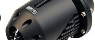
To visualize the servo drive, look at the picture below:
Servo drive for three way valve
Application and connection diagrams
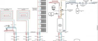
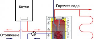
To prevent cold coolant from entering the jacket of the solid fuel boiler when it is warming up, a connection diagram for a three-way valve with a primary circulation circuit is used:
Three way valve connection
A three-way valve cuts off cold water from the return pipeline so that condensation does not appear on the internal walls of the solid fuel boiler chamber, which can significantly reduce the service life of the unit. The coolant circulates in the primary circuit until it heats up to the temperature set on the valve thermoelement, usually 40-50 ⁰C . Once this temperature is reached, the thermostat acts on the rod, gradually opening the flow of cold water from the heating system. For hydraulic adjustment of the entire system, a balancing valve is embedded in the small circuit. For the boiler piping circuit to work correctly, the circulation pump must be installed after the three-way valve, and not in front of it; this is a very common mistake.
A continuation of this scheme could be the organization of a secondary circulation circuit, which involves its own pump and three-way valve for heating. The connection is carried out according to the following scheme:
Three way changeover valve
In the secondary circuit, hot water from the boiler is added to the heating system as needed, and the pump ensures circulation in this circuit. The three-way valve and pump are controlled by a controller, which receives data on coolant parameters from sensors. Water is taken for the boiler between two circuits, where the coolant has a maximum temperature; the three-way valve is connected to the boiler in the primary circuit, as shown in the previous diagram.
Many manufacturers of boiler equipment install an additional circuit in their heating units to provide DHW consumers. In order to maintain the parameters of hot water supplied to the house, equipment for switching the main heat exchanger to the DHW circuit and back is installed inside the boiler. The operating principle and design of the three-way gas boiler valve involved in this process is not much different from the products described above. There is a slight difference in the design, which is a straight manifold; an element moves inside it, blocking the side pipes. The rod rotates using a servo drive upon command from the built-in boiler control unit.
Another area of application is the control of underfloor heating; for this, a three-way valve with a thermal head and a remote temperature sensor is usually used. The general scheme looks like this:
Three-way mixing valve with thermal head
The circuit ensures that all rooms are supplied with coolant at the same temperature. A three-way valve is needed to prevent overheating, since underfloor heating systems do not require the same hot water that comes from the boiler system. The pump creates circulation in all circuits, and the valve mixes hot coolant into the supply manifold as needed. Such a mixing unit is one of the simplest connection options; the circuit becomes more complicated when it is necessary to adjust the temperature in each room separately.
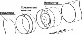
Servo drive: device and principle of operation
As usual, for clarity, let’s look at the servo drive device according to the figure:
Servo drive device
As you can see, the following components are located inside the servo drive:
- Electric motor.
- A gearbox consisting of several gears.
- The output shaft by which an actuator rotates a valve or other device.
- The potentiometer is the same negative feedback that controls the angle of rotation of the shaft.
- Control electronics, which is located on the printed circuit board.
- The wire through which the supply voltage (220 or 24 V) and the control signal are supplied.
Servo control signal
Let's now take a closer look at the control signal.
The servo drive is controlled by a pulse signal with variable pulse width.
For those who don’t know what we’re talking about, here’s another picture:
That is, the pulse width (in time) determines the magnitude of the shaft rotation angle.
Setting up such control signals is not trivial and depends on the specific drive.
The number of control signals depends on how many positions the output shaft can occupy.
The servo drive can be two-position (2 control signals), three-position (3 control signals) and so on.