Hello, dear readers!
Taking a quick glance at the heating radiator at home or somewhere with friends, at work, few people notice a small object installed at the end of the radiator. Meanwhile, this is an important element of the heating system - a thermostatic valve (TRV). It is thanks to him that comfortable temperature conditions are maintained.
You also save money on heating. I want to talk today about what kind of device this is and what pros and cons it has.
What is it and what is it for?
The thermal valve, which is also called a thermostatic valve, is designed for manual or automatic adjustment of the coolant supply from the heating main to the heating device. The device allows you to reduce or increase the heat flow through the pipes and maintain the required temperature regime. For example, when the room is cold, the valve opens on its own. If it gets too hot, it closes.
Purpose and scope
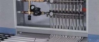
Thermostatic valves are designed for installation in any heating systems operating on liquid coolant. They are used in both residential and non-residential premises of apartments, private houses, offices, and administrative buildings. Outwardly similar to ordinary shut-off valves for shutting off water. They are mounted on one of the pipes leading to the radiator, directly in front of it.
Characteristics
Main technical parameters of valves:
- design - straight and angular;
- diameters - internal passage and external;
- maximum operating temperature;
- maximum permissible working pressure.
Direct thermostatic valves are installed if the pipe goes directly to the heater manifold. Angle valves are used when the location of the line and the radiator does not coincide and a bend in the pipeline is required. Diameters indicate the thickness of the walls and how much coolant can pass through the valve per unit of time, as well as the standard size.
For example, the specifications for a thermostatic product may indicate dimensions - ½, ¼ inch or any other. This is a marking according to the thread size, which on modern valves is inch. Exceeding the maximum operating temperature and pressure in the line will lead to improper operation of the valve or damage it.
What materials are they made from?
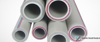
All valve components in direct contact with the coolant are made primarily of stainless steel, bronze or a cheaper alloy with it - brass. These materials withstand high temperatures and pressure well, and are resistant to corrosion. Parts designed to regulate the flow of coolant and the housings of electronic adjustment units are made of heat-resistant and wear-resistant plastic.
2007 Toyota Camry
April 10, 2013 in the category: TRV Thermostatic valve of a car air conditioner (working principle)
Question:
Hello. I have a 2007 Toyota Camry. The auto forum helped me a lot in learning about air conditioner repair, where I also learned about you. I really want you to help me sort out the problems with my car. The point is this. There were no accidents (I brought it from Japan myself), no one has climbed into the air conditioner over the past five years. The only intervention is to clean the radiators before each season.
Answer: First of all, those comrades who want to repair a car air conditioner must conduct a complete diagnosis of the entire system. The TRV valve is a primitive nozzle. If at some point in its life the expansion valve works, then replacing it is probably in vain. It's worth digging deeper. At the moment the defect appears, measure the readings of the pressure gauges in the system. Read more
Design and principle of operation
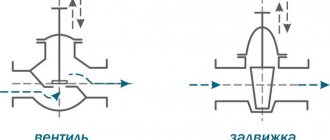
Thermostatic valves differ in design and operating principle depending on the type. A manual valve has a body with a stem and a spool that acts on the seat in the flow section. When the rod is turned clockwise, the flow area decreases; when rotated in the other direction, it increases. As a result, the coolant flow passing to the heating device per unit time changes.
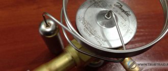
Inside the body of the automatic temperature control valve there is a thermal head with a thermal cylinder filled with kerosene, gas or a special liquid. When heated, the substances in the thermal head expand and change their physical state. The thermal balloon stretches, acts on the rod and causes it to move and be squeezed out of the bellows. The flow area is closed, and when the surrounding air cools, it opens again when the thermal cylinder returns to its original position.
Thermostatic valve dimensions
Pressure from the diaphragm is transmitted to the shut-off element using one or a pair of pushers, allowing it to move, closing and opening the valve seat. Below the locking element there is a spring with which overheating is regulated. By means of valves with external regulation it is possible to change the force of the spring pressure.
There are three main pressure values that cause the valve diaphragm to move:
The pressure of the sensing element is a function of the change in temperature inside the thermal cylinder of the charged substance.
- spring pressure (P1);
- thermal cylinder pressure (P2);
- equalizing pressure (P3).
The pressure of the sensing element is a function of the change in temperature inside the thermal cylinder of the charged substance. It acts on the diaphragm from above, causing the valve to open. Spring and equalizing pressure act together on the diaphragm from below, causing the valve to close. When the valve operates properly, the sum of the spring and equalizing pressures is equal to that of the thermal cylinder, i.e.:
P2 = P1+P3.
Advantages and disadvantages
As a technical means of controlling the flow of coolant, a thermostatic valve has a number of advantages:
- Allows you to maintain a comfortable room temperature in manual or automatic mode.
- Makes it possible to set the minimum temperature in rooms that are temporarily not in use.
- Helps save energy resources by at least 20%.
- Optimizes heating costs.
The disadvantages of a temperature control device include:
- More complex installation work on the heating system.
- The valve increases the hydraulic resistance in the pipeline.
- An additional threaded connection increases the likelihood of leaks.
- The valve is prone to clogging.
Brief history of the manufacturer
Electronic expansion valves were developed by Alco Controls based on mechanical control valves, the production of which began in 1924. The market demanded the creation of devices capable of maintaining the temperature of technological processes. The brand responded by developing a thermal expansion valve. Subsequently, the reliability and efficiency of products contributed to the conquest of the world markets for refrigeration and climate control equipment. The request from technologists for precision refrigeration systems posed a new challenge, to which the Germans responded by creating electronic regulators, which are often called electric.
Tips on how to choose
Installing thermostatic fittings in an apartment of a Soviet-built building will be justified only if the heating is very good. Otherwise, the valve will lower the temperature even more, and the apartment will be unacceptably cold. Modern new buildings are insulated using advanced technologies, so their heating efficiency is very high. Here the thermostatic valve will be of great practical importance.
In a private house, especially with individual heating, you cannot do without a thermal valve. Models with manual adjustment are suitable for small homes. For two-story cottages, it is better to buy automatic thermostatic fittings: running from one floor to another to manually adjust the temperature in each room is a very tedious task.
Popular manufacturers
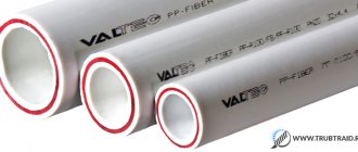
Leading positions in the production of thermostatic valves for heating systems belong to Danish manufacturers. The first and second places are occupied by Danfoss and Broen. In third place is the German brand Oventrop. Products from Heimeir, Herz, Honeywell, MNG, Schlosser, and Valtec are also in high demand on the domestic market.
What does the cost depend on and what is the approximate price?
How much a valve costs primarily determines the type of thermostatic device. Manual valves are cheaper than automatic valves. Thermostatic fittings with an electronic control unit are the most expensive, but they are an integral part of a modern smart home. The price, depending on the brand, ranges from 1000 rubles. for Valtec valves up to RUB 3,000. to devices from the Danish manufacturer Danfoss.
Types of electronic expansion valves
Today, the market offers developers of climate control equipment and refrigeration equipment two types of expansion valves: - pulse-modulating, the damper of which systematically takes the “open/closed” position. The cycle takes 6 seconds - when opened, the damper begins to let in refrigerant. The longer the “open” period, the greater the mass of the duct. The duration of the open position is determined by an electronic controller, more often called a thermostat, which monitors the overheating of the refrigerant.
Manufacturers guarantee 15-year operation of such expansion valves, during which the “open/closed” cycle will be repeated 80 million times. Among the advantages of this type of regulator is the ability to completely block the duct. The latter eliminates the design of climate control and refrigeration equipment from solenoid valves. In the event of an emergency power failure, the design provides for automatic shutdown of the refrigerant line; - smoothly regulating the flow of refrigerant - using stepper motors. The use of the latter eliminates water hammer. The stroke of the “damper” is determined by a tiny rotation of the rotor, not exceeding 1.8º, which is transformed into its translational movement. The profile of the blocked section has a complex configuration, ensuring a linear change in the volume of the refrigerant.
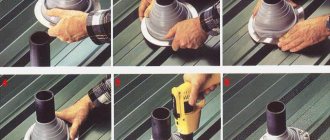
Installation and operation rules
It is quite possible to install a thermostatic valve with your own hands, following a simple diagram:
- Before starting installation, make sure that there is no coolant in the system.
- Remove the thermal head from the valve, cover the end of the stem with the protective cap, which is usually included in the kit.
- Install the valve by screwing it with American nuts between the radiator and the shut-off valve. There should be an arrow on the valve body that indicates the direction of coolant flow. The position of the thermostatic valve should be as horizontal as possible so that it does not overheat.
- First tighten the nuts by hand as much as you can, and then use a wrench to turn them one more turn. Be careful not to overtighten the nuts, otherwise they will burst.
- Secure the thermal head and set it to the minimum value. After filling the system, proceed to adjustment.
Adjusting the expansion valve
To properly adjust the temperature control device, install the thermometer in the area of the room where people are most often present. After 1-2 hours, check the temperature, if necessary, switch the regulator to a higher value. Repeat this until the room temperature becomes comfortable. There is no need to touch the adjustment knob in the future.
2.3. Steam ejector refrigeration units
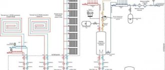
The cycle of a steam ejector refrigeration unit (Fig. 19 and 20) is also carried out using thermal rather than mechanical energy.
Rice. 19. Schematic diagram of a steam ejector refrigeration unit: ХК - refrigerating chamber; E - ejector; KD - capacitor; RV - pressure reducing valve; N - pump; KA - boiler unit
Rice. 20. Scheme of a steam ejector refrigeration unit with a mixing condenser
In this case, compensating is the spontaneous transfer of heat from a more heated body to a less heated body. Steam of any liquid can be used as a working fluid. However, the cheapest and most accessible refrigerant is usually used - water vapor at low pressure and temperature.
From the boiler plant, steam enters the ejector nozzle E. When steam flows out at high speed, a vacuum is created in the mixing chamber behind the nozzle, under the influence of which refrigerant is sucked into the mixing chamber from the refrigeration chamber of the cold room. In the ejector diffuser, the speed of the mixture decreases, and the pressure and temperature increase. Then the vapor mixture enters the condenser KD, where it turns into liquid as a result of heat q1 being removed to the environment. Due to the multiple decrease in specific volume during the condensation process, the pressure decreases to a value at which the saturation temperature is approximately 20 °C. One part of the condensate is pumped by pump H into the boiler unit KA, and the other is subjected to throttling in the valve RV, as a result of which, with a decrease in pressure and temperature, wet steam with a slight degree of dryness is formed. In the heat exchanger-evaporator XK, this steam is dried at a constant temperature, taking away heat q2 from the cooled objects, and then again enters the steam ejector.
Since the mechanical energy costs for pumping the liquid phase in absorption and steam ejector refrigeration units are extremely small, they are neglected, and the efficiency of such units is assessed by the heat utilization coefficient, which is the ratio of the heat taken from the cooled objects to the heat used to implement the cycles.
To obtain low temperatures as a result of heat transfer to a “hot” source, other principles can be used. For example, the temperature can be lowered as a result of water evaporation. This principle is used in hot and dry climates in evaporative air conditioners.
Frequent errors and problems during installation
The most common mistake is installing a thermostatic valve without using a shut-off valve. The fact is that the device is not designed to completely block the flow. In addition, the expansion valve will have to be cleaned periodically, and for this it is necessary to turn off the coolant supply. This can only be done using a crane.
The second mistake is to install the thermostatic valve so that it ends up at the intersection of warm air flows from a heating pipe or radiator. With this installation method, the thermostat overheats, that is, it receives incorrect data about the temperature in the room, and reduces the supply. The exception is devices with a remote sensor.
Last changes
09.09.2019
The organization is excluded from the Register of Small and Medium Enterprises
19.08.2019
The status of the organization was changed from “in the process of liquidation” to “liquidated”.
24.04.2019
The status of the organization was changed from “operating” to “in the process of liquidation”.
30.03.2019
The address of the organization is excluded from the register of the Federal Tax Service Addresses indicated during state registration as the location of several legal entities
09.10.2018
Added a note about the unreliability of address information
10.12.2017
The organization is included in the Register of Small and Medium Enterprises, category: microenterprise
14.11.2017
The address of the organization is included in the register of the Federal Tax Service Addresses indicated during state registration as the location of several legal entities
Expert advice
Several times I had to communicate with professionals in the design and installation of heating, and this is what they advise anyone who decides to install a thermostatic control valve:
- Install the device in an apartment only if the batteries have a power reserve of at least 30%.
- In older houses with a single-pipe heating system, use special valves with a large bore diameter.
- If there are 2 radiators in the same room, install a thermostatic valve on only one of them.
- The thermostatic head on cast iron batteries will practically not play any role due to the high thermal inertia of the metal. It is better to replace the radiator with an aluminum or bimetallic one.
Superheat calibration
Calibration of the superheat value should ensure the highest superheat value permissible at maximum load.
In an installation where the partial load reduction exceeds 65% of its capacity, the other measures listed below must be applied.
Two or more evaporators with the same parameters
Figure 14.11 shows two independent evaporators, each supplied by its own expansion valve with distributor. Each evaporator accounts for half of the total load.
| Figure 14.11 Independent power supply of two parallel evaporators of equal power, the operation of each of which is regulated by its own expansion valve and distributor: please note that the first section of the suction line is slightly inclined towards the siphon, which is done to prevent sedimentation of refrigerant and oil, distorting the sensor readings expansion valves. |
The solenoid valves are connected to a device to reduce the compressor capacity in such a way that one of them closes when the load on the compressor is reduced by 50%, cutting off one of the thermostatic valves. The remaining expansion valve ensures that performance is maintained at the required level.
The same simple system is applicable to different evaporators at different levels of compressor partial reduction. Different types of compressors can be connected in parallel or in series; In this case, it must be taken into account that the compressors located first will experience a higher load than those that follow, so the performance of the various valves and distributors must be adjusted to take this into account.
Single evaporator
Figure 14.12 shows a diagram of the installation of two expansion valves and two distributors on one evaporator.
| Figure 14.12. Single evaporator with two independent circuits, controlled by two solenoid valves, expansion valves and distributors. When the cooling load decreases, one of the solenoid valves closes, allowing a partial reduction in the generated cooling power. |
Each evaporator circuit has a supply of two distribution tubes, each of which, in turn, passes through its own distributor. The solenoid valves are controlled by the compressor partial load control device as previously described.
If the expansion valve, solenoid valve and distributor of circuit A are selected to cover 67% of the total capacity and 33% of the total maximum load is on circuit B, the switching of the solenoid valves will provide the operating parameters shown in Table 14.1.
Table 14.1. Switching sequence of solenoid valves when the thermal load changes.
| Thermal load (%) | Valve A | Valve B | Use of installed expansion valves (%) |
| 100 83 | Open | Open | 100 83 |
| 67 50 | Closed | 100 75 | |
| 33 16 | Closed | Open | 100 50 |