Currently, there is a large number of documents and technical instructions from developers that describe in detail the design of expansion valves, their operation, and the technology for their selection and installation.
Most documents indicate that the adjustment of the expansion valve is carried out at the manufacturer's factory and, as a rule, does not require additional adjustment. At the same time, the question arises: how to adjust the expansion valve if for some reason there is a need for additional adjustment? We recommend the following method. In addition to the commonly used pressure gauges, you need to install an electronic thermometer, the sensor of which should be mounted on the thermal expansion valve.
To maintain stability of the expansion valve setting over time, it is necessary to make it at a temperature in the cooled volume close to the compressor shutdown temperature (a setting that ensures stability at a temperature of 25 °C may lead to pulsation at a temperature of 20 °C). It is not allowed to adjust the expansion valve at high temperatures in the cooled volume!
TRV Danfoss
All refrigeration units are equipped with thermostatic valves (TEV), with the help of which the amount of refrigerant supplied to the evaporators of the refrigeration equipment is adjusted.
The Danfoss thermostatic valve is one of the best devices of our time, produced by the famous Danish concern of the same name. Menu:
- TRV Danfoss
- Replacing the expansion valve
- TRV valve 2
- Solenoid
- Ball
- Video
The principle of operation and the task that the thermostatic valve performs is to provide the evaporator with the required amount of refrigerant in a volume determined by the thermal load on the unit at a given time. For example, an air conditioner's expansion valve maintains the superheated vapor output within certain limits.
Kinds
According to their functional purpose, Danfoss valves are divided into the following types:
Thermal control valves ETS
Functional purpose: supplying coolant to the evaporators of refrigeration equipment and air conditioners. Thanks to the complete balance between valve and body, coolant flows in both directions. The valve closes very tightly.
Advantages:
- operates regardless of the direction of movement of the working medium in the unit, which is ensured by a balancing device.
- Various drive models make it possible to completely shift the valve in 2625 - 3810 steps within 8.4-12.7 seconds.
- If there is a direct current drive, the valve is moved at a speed of 150 steps per 1 second.
Thermostatic motorized valves AKV
With their help, the refrigerant is injected into the evaporators.
The adjustment is carried out using the pulse width method. This means that the width of the pulses sent by the unit controller determines the degree to which the valve opens. Advantages:
- thanks to the collapsible design, the valve assembly (nozzle) for the Danfoss AKV valve can be changed;
- the valve does not require adjustment during operation;
- The device is universal in design, since it is a solenoid and thermostatic valve at the same time.
Thermostatic valve T2 and TE2
To fill “dry” (unflooded) evaporators designed for low power, thermostatic valves T2 and TE2 are used. The rated cooling capacity of such units ranges from 380 W to 9,100 W with R404A/R507. They are used in conventional refrigeration units, heat pumps, air coolers, chillers, transport refrigerators, and ice generators.
They differ:
- large operating temperature range;
- the presence of a replaceable valve assembly;
- ease of setting the required performance;
- ease of storage.
Important! If necessary, you can supply a special adapter designed for both flanging and soldering.
The TE2 type includes the danfoss tx2 thermostatic valve, designed for automatic adjustment of the flow of refrigerants with the presence of fluorine in the evaporators of cooling units.
Designed to operate at pressures up to 28 atm at temperatures from -40 degrees to +10 degrees.
Thermostatic valve RNT
Controls the flow of liquid refrigerants into the evaporators of units. With its help, “dry” evaporators are filled, in which the thermal load on them is directly proportional to the overheating of the refrigerants. The device operates in a thermal range of -40 – + 50⁰С at a permissible operating pressure of 28 bar (for PHT 85 and PHT 125), and 20 bar (for PHT 300).
TRV TU/TC
The performance of TU/TC valves depends on:
- pressure created by the thermal cylinder filler;
- pressure during the boiling of the refrigerant;
- degree of spring tension.
Therefore, the adjustment of such thermostatic valves comes down to constantly maintaining a balance between the pressure level in the cylinder, which is formed on one side of the membrane, and the total pressure between the spring tension and boiling acting on the other side.
Such installations are used in conventional refrigeration equipment, heat pumps, air conditioners, coolers, etc.
They differ:
- lightness and strength;
- the presence of bimetallic fittings, which facilitates convenient and safe soldering;
- using stainless steel capillary tubes, which contributes to a long service life.
The overheating of this type of Danfoss valve can be adjusted using an adjusting screw.
Important! It is possible to mount with any MOP (maximum operating pressure) values, which helps protect the compressor from the occurrence of elevated pressures during boiling.
Thermostatic valve (TRV) TGE
This series is characterized by the presence of non-replaceable valve units.
Such valves have been developed for commercial purposes: they are used in high-performance air conditioning systems. The devices are capable of passing liquid refrigerant into “dry” type evaporators, in which the thermal load on the evaporator is directly proportional to the superheat of the refrigerants.
The advantages of the unit include:
- operation in conditions of high humidity, which is very important when equipping heat pumps;
- balancing of the valve assembly in any direction of flow of the working medium (valves of the TGE 20 and TGE 40 series);
- speed and ease of installation;
- there is a minimal risk of possible leaks, since all welds are laser.
The Danfoss Tgel-35 thermostatic valve is a direct-flow sealed product of the TGE modification that has a built-in valve assembly (R410 refrigerant) with static superheating 4K. Functions optimally at temperatures from -40 degrees. up to +10 degrees. and pressures not exceeding 46 atmospheres.
TRV TE5 – TE55
With the help of units, the supply of refrigerant to medium-sized refrigeration equipment is regulated. The valves are designed to fill “dry” (unflooded) evaporators with refrigerant, the flow of which can be judged by the degree of superheat when leaving the evaporator.
Thanks to the presence of a replaceable valve assembly, it is ensured:
- ease of installation;
- the best option to support a specific performance;
- the presence of channels that balance pressure.
Can be used in the temperature range from -60⁰С to +11⁰С!
TRV setting technology
The recommended technology for adjusting the expansion valve is to first bring the expansion valve to the limit mode at which pulsations begin. To do this, at a constant value of superheat (the readings of the thermometer and LP pressure gauge do not change), you need to slowly open the expansion valve until pulsations begin. If overheating pulsations appear (pulsations in the readings of the thermometer and pressure gauge), you need to close the expansion valve until the pulsations stop.
Attention! Never turn the adjusting screw more than one turn (the limiting mode leading to pulsation can occur when the screw is rotated 1/4 or even 1/8 turn).
After each change of setting (turning the adjusting screw), you should wait at least 15 minutes (in the future this will allow you to save time on setting). When the installation enters pulsating mode, it is enough to slightly close the expansion valve (for example, half a turn). In this case, the expansion valve will be set to the minimum possible superheat, which is provided by this installation, the filling of the evaporator with liquid refrigerant will be optimal, and the pulsations will stop.
Note: during adjustment, the condensing pressure should remain relatively stable, but its value should be as close as possible to the nominal operating conditions, since the performance of the expansion valve depends on it.
Unevaporated liquid particles (though it is unknown how long it will work in this mode, which can lead to very serious malfunctions).
Replacing the expansion valve
If refrigeration equipment functions intermittently, then you first need to find out the cause of the possible breakdown.
For example, when there is no supply of hot or cold air from the air conditioner, one of the reasons for its poor performance may be a clogged air filter.
To resume normal operation, the filter and other accessories should be cleaned and, as far as possible, prevent dirt and dust from entering them.
If the valve, for example, cannot equalize the pressure in the circuits, then it is best to replace it. By the way, such a technological process for troubleshooting as replacing the valve is a simple procedure that you can carry out yourself.
In addition, we offer a list of the most common breakdowns of refrigeration equipment when it is necessary to replace the device:
- productivity is too low;
- the presence of pressure pulsation, which is expressed by high productivity;
- very high pressure is formed at the suction;
- liquid refrigerant flows from the thermal cylinder or there is a leak;
- the compressor is constantly overfilled with liquid, which is caused by the valve’s throughput being too large;
- the unit is permanently closed;
- the valve does not respond to any method of influence;
- observation of constant fluctuations in temperature and pressure in the system.
ROUTINE MAINTENANCE AND PROCEDURE FOR SETTING THE TRV
Types of evaporators
The evaporator is one of the elements of a refrigeration machine in which the working substance boils due to heat supplied from a low temperature source. The vapor formed during the boiling of the refrigerant is sucked out of the evaporator by a compressor to carry out further processes in the refrigeration machine cycle. Depending on the underlying principle, evaporators are divided into a number of groups according to the nature of the cooled source:
- evaporators for cooling liquid coolants;
- evaporators for air cooling;
- evaporators for cooling solid media;
- evaporators-condensers.
depending on the circulation conditions of the cooled liquid :
- with a closed cooled liquid circulation system (shell and tube and shell and coil);
- with an open level of cooled liquid (vertical pipe, panel).
by the nature of filling with the working substance:
- flooded;
- non-flooded (irrigation, shell-and-tube with boiling in pipes, coil with top liquid supply).
Evaporators can be divided into other groups (depending on the surface on which the working substance boils; according to the nature of the movement of the working substance, etc.). Brines (aqueous solutions of NaCl, CaCl2 salts), water, alcohol, an aqueous solution of ethylene glycol, etc. are used as an intermediate liquid coolant in evaporators
With increasing brine concentration, the temperature at which solidification begins (crystallization) first drops, then becomes equal to the temperature of the cryohydrate point and then increases. The crystallization process ends regardless of the concentration at cryohydrate temperature. As ice or salt crystals fall out, with a decrease in the temperature of the brine, the remaining liquid phase will either increase its concentration (left curve) or decrease (right curve) to the state of a eutectic solution corresponding to the concentration of the cryohydrate point. For a NaCl solution, the cryohydrate temperature is -21.2°C, and the concentration is 28.9%; for CaC12 solution - -55°C and 42.5%, respectively
Technique for regulating expansion valves
When choosing a thermostatic expansion valve, it is also necessary to ensure that its throughput capacity matches the performance of the cooling device (evaporator), since only in this case is it possible to ensure absolutely stable operation of the controlled refrigeration unit. For this purpose, minimal overheating should be provided over the entire range of possible performance of the cooling device. As can be seen from Fig. 1, regulation can be stable only if the point of intersection of the operating characteristic curves of the cooling device and the operating characteristic of the expansion valve corresponds to the operating point of the installation's cooling capacity.
Rice. 1. Regulator and evaporator performance curves for the case of regulating the refrigerant supply to the evaporator using a expansion valve.
As soon as static superheat Δt3 is reached, the expansion valve begins to open and, when fully open, provides its rated capacity. In this case, the overheating increases by the amount of overheating of the open expansion valve Δtpo. The sum of the static overheating Δt3 and the overheating of the open expansion valve Δtpo constitutes the operating overheating Δtпн. Manufacturers of expansion valves set the value of static superheat, as a rule, in the range from 3 to 5 K. It can be changed in one direction or another by rotating the adjusting screw and pressing or releasing the spring. This operation leads to an equidistant shift of the operating characteristic of the expansion valve to the left or right, as a result of which it becomes possible to ensure stable control of the installation by positioning the operating characteristic of the expansion valve in such a way that it intersects the characteristic of the cooling device exactly at the operating point of the nominal cooling capacity. For cooling devices operating at very small temperature differences, it is necessary to provide a heat exchanger, which, by supercooling the liquid refrigerant, allows for increased superheating.
The setting of the expansion valve when shipped from the factory corresponds to most settings. If there is a need for additional adjustment, then you need to use the adjusting screw (see Fig. 2). When the screw rotates to the right (clockwise), the superheat increases; when rotated to the left (counterclockwise), the superheat decreases.
For T2/TU2 brand TRVs, a full turn of the screw changes the superheating temperature by approximately 4° at a boiling point of 0°C.
Starting with a TE5 expansion valve, a full turn of the screw gives an overheating temperature of about 0.5 K at a boiling point of 0°C.
Starting with TKE3 brand TEV, a full turn of the screw gives a change in superheat of approximately 3 ° at a boiling point of 0 ° C.
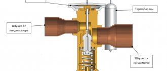
Rice. 2. Adjusting the expansion valve using the adjusting screw. The following adjustment method is recommended. Additionally, at the outlet of the pipeline from the cooling device, in addition to the pressure gauge (5), an electronic thermometer (3) is installed, the sensor (6) of which is attached to the thermal cylinder (4) of the expansion valve, as shown in Fig. 3.
Rice. 3. Diagram of the expansion valve adjustment method: 1 - thermostatic valve with internal alignment; 2 - cooling device; 3 - electronic thermometer; 4 — thermal cylinder; 5 - pressure gauge; 6 - primary sensor of the electronic thermometer. To ensure stability of the expansion valve adjustment over time, it is necessary to carry out it at a temperature in the cooled volume close to the temperature at which the compressor is turned off. It is not allowed to adjust the expansion valve (adjustment) at high temperatures in the cooled volume.
The recommended adjustment is to set the expansion valve to the limit mode at which pulsations begin. To ensure this at a constant value of superheat Δtper = tv.p -t0, it is necessary to slowly open the expansion valve until pulsations begin. In this case, the readings of the pressure gauge Рв.п and thermometer tв.п should not change. When the expansion valve is subsequently opened, pulsations in the readings of the pressure gauge Рв.п and thermometer tв.п may begin. From this moment you need to start closing the expansion valve until the pulsations stop (about half a turn of the control screw).
Rice. 4. Sequence of adjusting the expansion valve to the nominal mode. To avoid overfilling the evaporator with liquid, proceed as follows. By rotating the adjusting screw to the right (clockwise), increase the superheat until the pressure fluctuations stop. Then gradually turn the screw to the left until the oscillation starts, then turn the screw to the right by about 1 turn (for T2/TE2 and TKE by ¼ turn). With this setting, there are no pressure fluctuations and the evaporator operates in nominal mode. Changes in superheat within the range of ±0.5°C are not considered as fluctuations.
If the evaporator is overheating, this may be due to insufficient liquid supply. You can reduce overheating by rotating the adjusting screw to the left (counterclockwise), gradually reaching the point of pressure fluctuations. After this, turn the screw to the right one turn (for TEV types T2/TE and TKE by ¼ turn). With this setting, pressure fluctuations stop and the evaporator operates in nominal mode. Changes in superheat within the range of ±0.5°C are not considered as fluctuations.
If the expansion valve is adjusted to the minimum possible superheat required for the normal operation of this refrigeration unit, the filling of the cooling device with liquid refrigerant will be achieved at the nominal level, and the pulsations in the superheat value of the refrigerant vapor will stop. During the process of adjusting the expansion valve, the condensation pressure must remain relatively stable and close in value (Рк ~ Рк.н) under nominal operating conditions, since the cooling capacity of the expansion valve depends on them.
When adjusting, the following complications are possible:
1. It is not possible to achieve pulsations by adjustment.
This means that when the expansion valve is fully open, its performance is lower than that of the cooling device. This is due to the following reasons: either the flow area (f) of the expansion valve is small, or there is not enough refrigerant in the installation and an insufficient amount of liquid refrigerant from the condenser enters the expansion valve inlet.
2. It is not possible to eliminate pulsations after they occur.
This means that the performance of the expansion valve is higher than the capacity of the cooling device. This is due to the fact that either the flow area (f) of the expansion valve is too large, or the cooling device does not have enough liquid refrigerant.
Adjustment of the expansion valve is impossible when the superheat reaches a higher value (this occurs when the expansion valve is practically closed, the evaporation pressure is low, and the total temperature difference between the air temperature at the inlet to the cooling device tb1 and the boiling point of the refrigerant t0 is large). This means that less vapor is generated in the cooling device than the compressor can absorb, i.e. the cooling capacity of the cooling device is insufficient.
Therefore, if it is not possible to find a setting mode that eliminates pressure pulsations, it is necessary to replace the expansion valve, or replace the seats with holes (cartridges), if the design of the expansion valve provides for a set of replaceable cartridges. In this case, in order to reduce consumption, you need to replace the expansion valve or change the cartridge with the hole. If the superheat in the evaporator is too high, the throughput of the expansion valve is small. Then, to increase consumption, you also need to change the cartridge. Danfoss TE brand expansion valves are supplied with a set of replaceable cartridges. TKE brand TRVs have a fixed seat hole.
The throttle (or nozzle) opening of many expansion valves is made in the form of a replaceable liner, which makes it possible to provide a new value for its performance by simply replacing this element. The thermoregulating (power, control) path of the expansion valve, i.e. a complex consisting of the upper part of the expansion valve (the supra-membrane cavity that forms the temperature-regulating element), a capillary tube and a thermal cylinder, is also sometimes replaceable, which allows you to select the best option for filling the thermal cylinder (steam, liquid or adsorption filling), most suitable for the specific operating conditions of a given installation.
Rice. 5. Replacement of the replaceable expansion valve insert and replaceable cartridges.
Temperature difference
The temperature difference across the evaporator is calculated as follows:
ΔT=Ta1-Ta2,
where ΔTa is in the range from 2 to 8 K (for tube-fin evaporators with forced air).
In other words, during normal operation of the refrigeration unit, the air passing through the evaporator must be cooled not lower than 2 K and not higher than 8 K.
Rice. 2 – Scheme and temperature parameters of air cooling on the air cooler:
Ta1 and Ta2 – air temperature at the inlet and outlet of the air cooler;
- FF – coolant temperature;
- L – equivalent length of the evaporator;
- T is the boiling point of the refrigerant in the evaporator.
Lamellar heat exchangers
We devote a series of articles to the design and application of finned heat exchangers used in central air conditioners (AHU) and air handling units. Too often, some heat exchanger manufacturers provide incorrect data, which gives designers reason to expect unrealistic results. In this article we will reveal problems from the air side: the impact on the performance of the lamella profile (fins) and pressure loss. Let us also lightly touch on the problem of the influence of condensation in the case of a cooling battery.
Introduction
Let us consider the case of forced airflow of a heat exchange battery. In this case, the speed of air movement lies in the range from 1 to 5 m/sec. The air flow between the lamellas is not laminar, even though it may seem so in some cases. Laminar flow cannot be stable here, since an intense vortex is created behind each tube. Even if the laminar air flow manages to bypass this vortex, it will “bump into” the next tube (see Fig. 2). So we will consider an ordinary turbulent flow, for which equations of the type 1/a = C*v^n are most often used, where a is the air heat transfer coefficient, v is the air speed, C and n are the corresponding coefficients. A similar equation applies to the air side head loss delta p = D*v^m. The coefficient n fluctuates, according to the data given in the literature, from 0.41 to 0.9, the coefficient m fluctuates between 1.3 and 2, more often 1.8 [1].
The most accurate method for determining all coefficients is the American standard ARI 410 [2]. It is based on measuring the performance of several heat exchangers with different numbers of rows and different fin pitches. Hot and cold water (both dry and wet cooling) were used as the working fluid. More than 30 laboratory tests are typically performed for one type of heat exchanger geometry and profile. The measurement results fall on a straight line in a logarithmic diagram (see Fig. 3). The accuracy of the method is ±5% of the total productivity for any combination of rows, contours, and finning steps.
conclusions
Obviously there are no miracles in technology. Higher productivity is paid for by a larger surface area or greater pressure losses.
Manufacturers usually indicate air resistance lower than the real one. We advise you to show healthy pessimism and test at least one heat exchanger when determining the qualifications of the supplier. The same applies to checking the performance of the heat exchanger.
The reliability of a heat exchanger manufacturer can also be preliminarily checked by asking about the calculation methodology used in its calculation program. The greatest difference between the real and the indicated calculated value may occur in coolers, in the case when the calculation did not take into account the drops of condensate formed on the surface of the lamella.
For coolers operating in conditions of condensation formation, the use of a hydrophilic coating reduces the loss of air pressure and increases the value of its speed at which a drop eliminator should be used.
In water cooling installations - chillers - production, only proven heat exchangers/condensers are used.
Thermostatic valves
Thermostatic valves (TEVs) are the most common regulators for supplying refrigerant to evaporators. Adjusting the expansion valve superheat set point significantly affects the cooling capacity of the equipment.
If the expansion valve is adjusted to high superheat or its thermal bulb is not installed correctly, then this is the cause of low suction pressure. If the overheating setting of the expansion valve is set incorrectly, then perform the following operations:
- measure the temperature in the suction pipeline at the place where the thermal cylinder is attached;
- determine the pressure in the suction pipeline at the place where the thermal cylinder is attached.
If the expansion valve has an external equalization line, then the pressure gauge installed on it directly and accurately displays the detected pressure. For expansion valves with internal equalization, the pressure is determined using a pressure gauge at the compressor suction valve. Then the calculated pressure drop in the suction pipe between the thermostatic expansion valve and the compressor suction valve is added to this value. The sum of the pressure gauge and the calculated pressure drop is approximately equal to the pressure in the pipeline at the location of the thermal cylinder.
The unit operates with increased load when its performance is insufficient or the cold consumption has increased. The only solution to this problem is to replace the unit with another more productive one. A significant thermal load on the evaporator occurs at high fan speeds, resulting in increased suction pressure. You can reduce the fan speed and at the same time change the difference between the temperature of the air flow passing through the evaporator and the boiling point of the refrigerant. The recommended temperature difference is usually 11°C for air conditioning and 6 - 9°C for refrigeration. Industrial blast freezing of fruits from
Frame, crankcase, crankcase
The main requirements that the frame, crankcase and crankcase structures must satisfy are strength and rigidity . The latter determines the accuracy and preservation of the relative position of the axes of the compressor movement mechanism during operation. Frames, crankcases and crankcases absorb the forces generated by compressor operation and transmit torque , unbalanced forces and moments of inertia of moving masses, as well as the weight of the compressor, .
Crosshead compressor frames are under atmospheric pressure. Openings, hatches and openings in frames are sealed with lightweight covers and casings. Horizontal opposed compressors predominantly use multi-bearing box-section frames, creating a lightweight and rigid structure.
The crankcases and crankcases of crosshead compressors are under pressure from the intake refrigerant vapors. This pressure during compressor operation does not exceed 0.6 MPa for most refrigerants . However, during long periods of parking of the machine, the pressure in the crankcase may increase to a value determined by the ambient temperature. Therefore, testing for the strength and tightness of crankcases and corresponding housing parts of compressors operating in automatic mode is carried out according to the same standards as for housing parts on the discharge side.
Frames, crankcases and crankcases are usually made from cast iron, sometimes welded from sheet steel . In small compressors of transport vehicles, aluminum alloys are used to reduce weight. In most cases, cast parts must be subjected to aging (artificial or natural) to maintain the correct position of the axes and planes, and welded parts must be subjected to annealing . The same basic requirements —the exact relative position of axes and planes—are also applied to machining. In addition, the sealing planes (surfaces) of crankcases and crankcases must allow assembly with counter parts to ensure tightness . Permissible deviations in the seating dimensions of frames, crankcases and other compressor parts, as well as the microgeometry of the main seating surfaces are given in specialized literature.
Refrigerants - basic definitions, brief historical overview, designations
The refrigerant (refrigerant) is the working fluid of the refrigeration machine, changing its state of aggregation in different parts of the refrigeration circuit. During the transition from liquid to gaseous state, which occurs in the evaporator, the refrigerant takes heat from the environment due to the endothermic nature of the evaporation process, thereby producing cold . Then the selected heat is removed from the refrigeration machine as a result of subsequent condensation of the refrigerant in the condenser and transferred to another medium, and the process of transition of the refrigerant from a gaseous state to a liquid is exothermic in nature.
In order for a substance to perform the functions of a refrigerant , it is necessary, first of all, that at atmospheric pressure its boiling point is as low as possible, the volumes of vapors formed during evaporation are insignificant, and the condensation pressure is not too high and easily achievable. In addition, the refrigerant must be non-aggressive towards structural materials and oils, as non-toxic, non-flammable and explosion-proof as possible. Finally, it is desirable that, under the conditions in which the most common refrigeration networks are found, its specific enthalpy is significant. In other words, it is impossible to find a substance that simultaneously satisfies all these requirements.
Water was used as the first coolant because, from 1755, it served “to produce frigories (negative calories)” in a laboratory setup created by William Gullen. Later, in 1834, the American Jacob Perkins made a compression machine running on diethyl ether, and in 1844, also an American John Gorrie, a machine with air compression and expansion. But the French did not remain in debt and in 1859 FerdinandCarre built an absorption refrigeration machine using ammonia , and four years later Charles launched a compressor running on methyl ether. Until the end of the 19th century. two more new refrigerants were used: carbon dioxide (CO2) and sulfur dioxide (S02), in addition, one of the already mentioned refrigerants - ammonia - is used not only in adsorption refrigeration machines, but also in compression ones (Linde).
These last three refrigerants, namely ammonia (R717), carbon dioxide (R744) and sulfur dioxide (R764), remained the most common until 1930. But with the introduction in 1930 in the United States, a new category of refrigerants: chlorofluorocarbons, well known by the acronym CFCs, all previously mentioned refrigerants except ammonia, have almost completely disappeared . However, starting in 1980, scientists began to raise alarm bells by drawing public attention to the harmful effects of CFCs on the environment. Therefore, manufacturers have begun to develop refrigerants that are less harmful to the future of the planet, some of which have already appeared on the market. These CFC replacement refrigerants come primarily from two chemical categories: chlorofluorocarbons, or HCFCs, and hydrofluorocarbons, or HFCs.
Although the number of widely used refrigerants has been significantly reduced, their range remains quite large. To facilitate their designation, a system of alphanumeric indices was introduced. This system is established for all chemical compounds whose composition does not always exactly match the CFC, HCFC or HFC categories we described above. They are designated by the letter R followed by three numbers, i.e. Rcdu, where:
- c (hundreds) is equal to the number of carbon atoms reduced by one;
- d (tens) is equal to the number of hydrogen atoms increased by one;
- and (units) is equal to the number of fluorine atoms.
To determine the chemical formula of a compound, its composition is supplemented with chlorine so that the total number of monovalent atoms, i.e., hydrogen, fluorine and chlorine atoms combined, is equal to 4 for methane derivatives, 6 for ethane derivatives, 8 for propane derivatives, etc. .According to "Textbook of Refrigeration Engineering" Pohlmann 1998
Gas compression - basic concepts
In production processes, significant quantities of gases and their mixtures are processed at pressures other than atmospheric; in addition, gases are also used for auxiliary purposes (for squeezing, mixing and spraying various substances). All these processes are carried out by compression or rarefaction of gases . Compression or rarefaction of a gas (change in volume) is accompanied by a change in its pressure and temperature.
Adiabatic, isothermal and polytropic compression and rarefaction. As is known from thermodynamics, a change in the state of a gas with changing volume and pressure can occur in three ways: isothermal, adiabatic and polytropic. The change in gas pressure during compression largely depends on whether, during compression, heat exchange occurs between the compressed gas and the surrounding external environment. In practice, such heat exchange is inevitable, and in many cases even necessary, for which artificial cooling of the compressed gas is used.
Theoretically, one can imagine two limiting cases of gas compression , and all real processes of gas compression will be intermediate between them.
In the first case, all the heat released during gas compression is completely removed outside, and the process of changing the state of the gas, i.e., changing its volume and pressure, occurs at one constant temperature; such a process is called isothermal. In the second case, on the contrary, all the heat released during gas compression remains completely inside the gas, increasing its temperature, while there is no heat loss to the environment; such a process is called adiabatic.
In reality, the compression of gases does not proceed isothermally or adiabatically, but in each particular case it only approaches one of these processes. Such a real process of gas compression, in which simultaneously with a change in volume and pressure there is also a change in temperature and heat removal to the outside, is called polytropic.
Heat
Heat is energy obtained from a change in temperature. Heat is transferred from a warmer body to a colder one. Heat is the temperature component of energy transfer during the operation of machine systems. Whereas work is the transfer of energy by a force that moves mass over a certain distance, heat is transferred from one body to another due to temperature differences . Heat transfers internal kinetic energy from the molecules of a warmer body to a colder one. This transfer of energy reduces the level of kinetic energy of the molecules of the warmer body, which produces a corresponding decrease in its temperature. At the same time the kinetic energy is equalized and the temperature of the colder body increases.
The transfer of energy that affects body temperature is called heat transfer . Although heat transfer occurs primarily in response to temperature differences, it is also caused by the force of friction - these are interactions that occur at the molecular level as the movement of bodies relative to each other. Such interactions change the kinetic energy of molecules between two surfaces. As a result of stretching the rubber band, the molecules move past each other, changing their speed and the temperature of the entire body. This change in thermal energy is a conversion process, where part of the work done to move the body is stored in the form of energy. This section describes the various types of thermal energy and heat transfer between bodies.
Requirements
Western Australian regulations require milk to be cooled to 4°C or below within 3.5 hours of milking. However, to obtain a high-quality product, it should be cooled to below 4°C as quickly as possible. In addition, it is very important to store milk at a temperature below 4°C between milking operations.
Cooling systems
Direct refrigeration systems (direct evaporation of the refrigerant) and thermal storage systems are the main systems used on dairy farms to cool dairy products. Direct chill systems include a refrigeration unit that supplies a cooling refrigerant that removes heat from the milk stored in the bulk tank.
Thermal storage systems use a refrigeration unit to cool the refrigeration medium, which is stored in a thermal storage tank. The refrigeration medium is then used to cool the milk using a heat exchanger before the milk enters the bulk tank. Typically, milk enters the bulk tank at a temperature below 4°C.
Rice. 1. Typical milk storage . Shown is a refrigerated tank (milk cooler), transfer pump, built-in cleaning filter and plate cooler.
Pre-cooling
Pre-cooling with a plate cooler helps reduce bacterial growth and also reduces the load on the refrigeration unit. This significantly reduces cooling costs. To check the effectiveness of pre-cooling:
·measure the temperature at the water inlet;
Measure the temperature at the milk outlet. Ideally, the difference between the specified inlet and outlet temperatures should be 3°C or less. In practice, inefficiency is often due to the following reasons:
· inadequacy of the number of plates for a given milk flow;
· inadequacy of the water flow rate (the water flow rate should be 2.5 - 3 times greater than the maximum milk flow rate);
· incorrect installation - manufacturers recommend installing single-pass plate coolers in such a way that milk is supplied from below. To prevent sediment from depositing between the plates, it should be filtered before passing through the plate cooler. Plate coolers must be washed with filters installed!
Temperature between milkings
Regulating milk temperature between milkings is very important to maintain quality during tank storage. Cooling should “turn on” before the temperature reaches 4°C.
Education
All new milker(s) or farm employees must receive full training in the operation of the milk cooling and storage system before they are assigned responsibility for the operation of the unit.
Department of Agriculture - Western AustraliaFarmnoteNo 36/99 Authors: JRM (Ian) and Bell SJ Gallagher
Boiling
Boiling is a process of intense evaporation that occurs when the vapor pressure of a liquid is equal to the ambient pressure. To raise the vapor pressure to this level, a large amount of energy must be transferred to the liquid. The energy increases the temperature of the liquid to its saturation temperature. As the temperature of a liquid increases, the kinetic energy and the number of molecules separated from the liquid increase, and the vapor pressure at the surface of the liquid also increases. Molecules with high energy at the surface of the liquid break bonds and overcome the force of attraction. As they rise above the surface of the liquid, their mass increases, and the pressure acting on the surface of the liquid increases the vapor pressure . Once the vapor pressure equals the surrounding atmospheric pressure, the atmosphere can no longer prevent molecules from separating from the liquid, and boiling . For example, to raise the vapor pressure of water at room temperature to atmospheric pressure, the temperature of the liquid must be raised to 100°C. This increase in temperature supplies kinetic energy that separates enough molecules from the surface of the liquid that their total mass causes a vapor pressure of 101.3 kPa. Boiling occurs when the temperature and vapor pressure of a liquid intersect the saturation temperature .
boiling process requires a continuous supply of additional energy to maintain steam pressure. Energy produces the necessary transformation of the potential energy of molecules to change the phase of latent heat.
Boiling is characterized by significant movement and the rapid appearance of vapor bubbles throughout the entire volume of liquid. Bubbles expand and rise to the surface of the liquid as a result of the difference in density between the liquid and the vapor. The bubbles collapse at the surface and release steam into the environment. When vapor bubbles near the surface of a liquid break, tiny droplets of liquid are released into the atmosphere. It is these drops of water that make the steam visible above the vessel.
Condensation
Condensation is a process involving latent heat, as a result of which steam passes into the liquid phase . This occurs whenever saturated steam is exposed to a temperature below its saturation temperature . Since saturated steam exists at the boiling point of a liquid, it is at the lowest temperature possible to maintain the properties of steam. Therefore, a minimal decrease in temperature causes the steam to condense . When saturated steam cools, its molecules are subject to the forces of the liquid molecular structure and return to the liquid state.
If condensation occurs in a closed vessel, the density (kg/m3) and vapor pressure decrease . As a result, there is a corresponding decrease in the saturation temperature of the liquid. To maintain the condensation process under such conditions, the temperature of the liquid must continuously decrease to match the decrease in saturation pressure. Conversely, if steam is continuously supplied to a vessel to replace the mass of steam that condenses and is removed from the vessel, its density, pressure and saturation temperature will be constant. This method of condensation is used in machine cooling and continues until the heat is completely extracted from the steam.
Evaporation
Evaporation is a subtle thermodynamic process caused by the slow transfer of heat from a fluid to its surroundings. The process of evaporation produces rapid changes in the volume or mass of a liquid. Evaporation occurs as a result of the absorption of thermal energy from the environment by liquid molecules due to a small temperature difference. This increase in energy correspondingly increases the kinetic energy of the fluid. When kinetic energy is transferred through collisions, some molecules near the surface reach speeds that are much higher than the average speed of neighboring molecules. When some high-energy molecules approach the surface of a liquid, they break bonds, overcome the force of gravity and pass into the atmosphere as vapor molecules.
Vaporization by evaporation occurs if the vapor pressure above the liquid is lower than the saturation pressure, which corresponds to the temperature of the liquid. In other words, evaporation occurs when the vapor pressure and temperature lines of a liquid intersect at the saturation temperature line at a point below atmospheric pressure. These conditions are on the saturation temperature line below the horizontal line of vapor pressure, which corresponds to the temperature of the liquid.
The volume of evaporating liquid continuously decreases as molecules separate from the surface and penetrate into the surrounding atmosphere. After separation, some vapor molecules collide with others in the atmosphere, transferring some of their kinetic energy. When the reduction in energy reduces the speed of the vapor molecules below the level of separation from the liquid, they flow back and thus regain some of the lost volume. When the number of molecules leaving the liquid equals the number falling back, a state of equilibrium . Once this condition occurs, the volume of the liquid will remain unchanged until changes in vapor pressure or temperature produce corresponding changes in the rate of evaporation.
TRV valve 2
Thermostatic valve tn 2 r 134 is a fairly precise unit with which the supply of refrigerants is regulated, depending on the intensity of their boiling in the evaporators. Flow regulation is carried out by the presence of specific temperature indicators and pressure of the vapor-type refrigerant at the exit from the evaporator.
Thermostatic valves of the tes 2 type TSV 2 models with external equalization are usually made of brass and are designed to operate in systems with an optimal pressure of 34 bar. They can easily withstand external influences and have a long service life.
Repairman's Guide
| 14. The valve is too weak. 14.1. ANALYSIS OF SYMPTOMS |
A malfunction caused by insufficient throughput of the expansion valve covers a large number of different failures in which similar symptoms appear. The subject of this section is to examine these symptoms. If necessary, you can review sections 3 and 4 again. A) Effect on the expansion valve/evaporator system
To illustrate a malfunction caused by a small expansion valve, let us take as an example a expansion valve in which the hole diameter is too small due to an error in choosing a replacement flow section (section b was installed instead of section B, see Fig. 14.1). As a result, the liquid flow becomes insufficient and the last drop boils away inside the evaporator very early (point 1). Since the last drop has boiled away too early, the vapor will be exposed to the air passing through the evaporator for a very long time, due to the increase in the length of the overheating region compared to the norm. Therefore, the temperature in the thermal bulb (point 2) will be abnormally high (in the limit, the suction line temperature can become almost equal to the ambient temperature). The evaporator is very poorly filled with refrigerant, the mass flow of refrigerant and cooling capacity drop. In the room that is being cooled, the temperature rises and the client is forced to ask for troubleshooting because “it has become very hot.” As the temperature in the cooled volume increased, the air temperature at the evaporator inlet also increased (point 3). Due to the fact that too warm air enters the evaporator (point 3), and the cooling capacity is low, the air is poorly cooled and the temperature of the air stream at point 4 is abnormally high. B) Effect on the evaporator/compressor system When passing through the evaporator, each kilogram of liquid that boils away, absorbing heat, produces a certain amount of steam.
Since the expansion valve does not allow enough liquid to pass through, the amount of steam produced drops greatly. However, the compressor can potentially absorb much more steam than the evaporator produces, so the boiling pressure becomes abnormally low ( point 5 in Fig. 14.2). Because the boiling pressure tends to fall and the air temperature at the evaporator inlet rises, the total temperature difference Abtotal at the evaporator becomes abnormally high. As the boiling pressure drops, the boiling point also drops according to the relationship between temperature and pressure for a given refrigerant. At the same time, the temperature of the thermal cylinder increases (point 2) and overheating will certainly be very high. If we are dealing with an air conditioner, then during normal operation the boiling point is always above 0°C. However, due to the fact that the performance of the expansion valve is insufficient, the boiling pressure is too low, the boiling point may be negative and the pipeline at the outlet of the expansion valve will in this case be covered with frost formed from the condensate of vapors contained in the cooled air ( point 6 in Fig. 14.2). B) Effect on the compressor/condenser system
Due to the fact that the superheat is very high and the temperature of the thermal cylinder is increased, the temperature of the vapors sucked into the compressor is also increased. The motor cooling of hermetic or sealless compressors is carried out due to the suction vapors, and since their temperature is increased, the cooling of the electric motor will deteriorate. As a consequence, the compressor will become hotter (instead of being cold) in the area of the suction valve ( point 7 in Fig. 14.3), and in the lower part of the crankcase (in the area where the oil is located) it will be extremely hot ( point 8 ). Thus, due to the large superheat in the suction line, the entire compressor will be abnormally hot. Note that an increased gas temperature in the suction line leads to the fact that the gas temperature in the discharge line ( point 9 ) will also be higher. Moreover, we saw that cooling capacity had become abnormally low. However, the condenser parameters were selected based on the heat transfer condition calculated based on the normal cooling capacity. Therefore, it turns out that the capacitor becomes oversized! If the method used in the installation for regulating the condensing pressure does not allow changing the air flow through the condenser, the air temperature drop across the condenser becomes lower than usual and at the outlet from it (point 10) the air temperature will be less high. In addition, due to the low throughput of the expansion valve, the oversizing of the capacitor leads to other undesirable consequences for the installation. Thus, due to a lack of liquid in the evaporator, in the condenser and in the liquid receiver, its amount will be excessive. Since the condenser is oversized, this liquid will be cooled much better and, therefore, in accordance with the relationship between temperature and pressure, the condensation pressure will drop, and the magnitude of its drop will depend on the method of regulating the condensation pressure used in the installation. Finally, bearing in mind that the capacitor is oversized, we can expect premature condensation of the last gas molecule, which will occur at point 11 (see Fig. 14.4), thereby causing an increase in the length of the section of the capacitor where supercooling occurs. As a result, the value of subcooling measured at the outlet of the condenser (at point 13 ) will apparently be high. ATTENTION! DO NOT CONFUSE PROBLEMS CAUSED BY LOW FLOW CAPACITY OF THE TRAVEL VALVE WITH PREMATURE CHROCKING OF THE REFRIGERANT BEFORE ENTERING THE TRAVEL VALVE. To be confident in your diagnosis, you must ensure that there are no blockages or premature throttling in the fluid line that could cause you to erroneously conclude that hypothermia is normal. Therefore, your standard for estimating the amount of subcooling should be the measured liquid temperature at the outlet of the condenser (point 13 ). Otherwise, a closed liquid valve at the outlet of the receiver (low temperature at point 12 ^1) or a clogged filter-drier (low temperature at point 14 ^1), as well as boiling at the inlet of the expansion valve (low temperature at point 15 ^1 ) can create the illusion of normal hypothermia (malfunctions caused by premature throttling will be discussed a little later). IMPORTANT NOTICE! Subcooling should not be confused with liquid line temperature. Subcooling is defined as the difference between the condensing temperature corresponding to the OBD pressure gauge reading and the liquid refrigerant temperature measured at the condenser outlet (see section 2.2).
| 14.2. GENERALIZATION OF SIGNS INDICATING LOW CAPACITY OF TRV |
Attention! For example, in air conditioners, the LP value corresponding to a boiling point of 0 ° C can be considered reduced if the air temperature at the evaporator inlet is about 25 ° C (Lvtot = 25 - 0 = 25 K), at the same time, the LP value at the same a boiling point of 0°C can be considered normal for an air temperature at the evaporator inlet of 18°C (Lvtot = 18-0 = 18 K). Return to Section 7 if necessary.
| 14.3. ALGORITHM FOR DETECTING LOW CAPACITY OF TRV |
If the superheat is increased, this necessarily indicates a lack of liquid in the evaporator. If subcooling is normal, then the condenser is filled with liquid. In that case, why doesn't it reach the evaporator? ► This could mean either a blockage in the fluid line (in which case we will have premature throttling). ► Or its entry into the evaporator is prevented by the expansion valve due to its low throughput.
| 14.4. CONCLUSION |
Why did the compressor stop cooling?.. Let's see... Oh! The boiling pressure has dropped... What could have happened?.. Insufficient air flow through the evaporator?.. No, the overheating is enormous... There is not enough refrigerant in the circuit?.. It can’t be, because subcooling is normal.. Maybe a plug has formed on the liquid line? .. NO, since there is no temperature difference... Therefore, it can only be... TRV PERFORMANCE TOO LOW!
| 14.5. PRACTICAL ASPECTS OF ELIMINATING MALFUNCTIONS CAUSED BY LOW CAPACITY OF TRV |
Once you have verified that the reason for the abnormal operation of the installation is insufficient performance of the expansion valve (drop in cooling capacity, drop in boiling pressure, increased superheat, normal subcooling, lack of temperature difference in the liquid line), you should determine exactly what defect or error caused low performance of the expansion valve to eliminate them. Therefore, now we will study various reasons that can lead to a decrease in the performance of the expansion valve and cause the appearance of symptoms characteristic of this malfunction. Incorrectly selected expansion valve with a small bore diameter Let us recall that for a given refrigerant the actual performance of the expansion valve is mutually dependent on the condensation and boiling pressures (see section 8.1 “Method for setting the expansion valve”). Never change the TPV setting unless you are absolutely sure of your diagnosis. If you wish to do this, please take the necessary steps to revert to the original setting if necessary. The control path of the expansion valve is destroyed. This malfunction often occurs due to poor fastening of the capillary connecting the control cavity of the expansion valve membrane to the thermal cylinder. As a rule, leakage appears either at the point of supply of the capillary to the expansion valve, or at the point of its connection with the thermal cylinder as a result of excessive vibrations of the capillary, as well as in the capillary itself in the case when there is repeated friction of the capillary when it vibrates against any metal part of the installation. Accurately establish the location of the damage to the capillary in order to replace it with a similar one, paying attention to the nature of the damage and the location of the destruction, so that when replacing you do not repeat the mistake made earlier during installation! Note. Such a breakdown leads to complete blocking of the flow area of the expansion valve, which will very quickly cause the compressor to stop based on a signal from the LP safety relay (see section 4 “Operation of the expansion valve”). The thermal expansion valve is installed downstream from the insertion point of the external pressure equalization tube. Consider the diagram in Fig. 14.8, which shows an expansion valve with an external pressure equalization tube installed incorrectly in relation to the thermal bulb (this type of expansion valve is described in section 46).
If the seal that ensures tightness between the low-pressure receiving chamber (item A) and the throttling chamber loses its tightness as a result of wear caused by prolonged friction against the guides of the expansion valve needle rod, there is a danger of partial penetration of liquid into cavity A. From this cavity, a small amount of liquid through the equalizing tube can reach the outlet of the evaporator and lead to abnormal cooling of the thermal cylinder, thereby causing unjustified closure of the expansion valve. If a leak exists, the difference in temperature between points B and C can be easily detected by simply touching the two pipes. To avoid this problem, it should be considered preferable to mount the thermal bulb upstream from the insertion point of the equalizing tube at point C at a distance of at least 10 cm from each other (see also section 49 “Problems of the thermal expansion valve bulb”). The control path and the thermal cylinder are not filled with the same refrigerant that is used in the installation . Remember that the pressure developed in the thermal cylinder is the only force that is used to open the expansion valve. When the temperature of the thermostat increases, the pressure inside it also increases and this increase in pressure causes the expansion valve to open (see section 4 “Operation of the expansion valve”). In Fig. 14.9 presents various options for the operation of the expansion valve.
Pos. 1. This expansion valve is designed to supply the direct expansion evaporator in a small air conditioner and operates on R22. The boiling point is 4°C, and the superheat is maintained at 7 K. Therefore, when the temperature in the thermal cylinder exceeds 11°C, which for a control path containing R22 is equivalent to a pressure of 6 bar, the expansion valve will begin to open. That is, the opening pressure of the expansion valve is 6 bar. Therefore, for the expansion valve to start opening, the pressure in the thermal cylinder must reach 6 bar. If the pressure in the thermal bulb is low 6 bar, the expansion valve will be closed. Pos. 2. Let’s imagine that, as a result of an error during installation or repair, a thermostatic element with a thermal cylinder filled with R12* was installed on the expansion valve. When the temperature of the thermal bulb is 11 °C, the pressure in it will be only 3.4 bar and, therefore, the expansion valve will be completely closed. Pos. 3. In order for the expansion valve to start opening, the pressure in the thermal cylinder must rise to 6 bar. For R12 this means that the temperature of the thermal bulb must rise to 27°C! In this case, the overheating becomes enormous and the evaporator will contain so little liquid as if the performance of the expansion valve was insufficient! Some designs of expansion valves have a replaceable control path, which consists of a membrane assembly, a capillary and a thermal cylinder (editor's note). How to identify this anomaly? First you need to make sure that the malfunction is not caused by another reason. After this, it is necessary to determine, on the one hand, what refrigerant is used in the installation, and on the other hand, what refrigerant is filled with the thermal cylinder and the control path of the expansion valve...
The type of refrigerant filling the control path of the expansion valve is always indicated on the top cover of the membrane assembly, sometimes in the form of a color code (usually yellow means R12, green - R22 and purple - R502). However, the proliferation of new refrigerants may complicate the situation somewhat, because some of them (especially transition mixtures such as HCFC, which do not require replacement of expansion valves) can work without problems using expansion valves that are not designed to work with these refrigerants! (See section 56 “Problems arising from the advent of new refrigerants”). If the name of the refrigerant is not indicated on the installation and you are in doubt what type it is (a good way to determine the type of refrigerant is the relationship between pressure and temperature), never hesitate to ask the customer, who has the necessary documentation for the installation and is usually very good knows its history. Mechanical jamming of the expansion valve rod and its jamming when opening. This malfunction may have a purely mechanical cause, and then the expansion valve should simply be replaced. However, it can also be caused by contamination of the refrigeration circuit by the presence of moisture, dirt or foreign particles that stick to the moving parts (in some extreme cases, the internal surfaces of the expansion valve can become sticky and stick to your fingers). In the case of a dirty circuit, the repairman should not be satisfied with cleaning the expansion valve and replacing the filter drier. He should think about the undesirable consequences of such contamination (especially on the compressor) and check the oil for acid content. If the test results are positive, he must take all necessary measures to completely clean the system, otherwise the compressor (sealed or sealless) has a serious chance of quickly failing. Clogged filter at the inlet to the expansion valve Like the previous fault, this anomaly (fortunately quite rare) means that the refrigeration circuit is extremely dirty and the filter drier is ineffective. The same measures should be taken as in the previous case. Abnormal condensing pressure drop We have seen that the performance of the expansion valve is largely determined by the line pressure at the inlet to the expansion valve (see section 8.1 “Why you need to regulate air-cooled condensers”). Whatever the reasons for the lack of such regulation (malfunction of the condensation pressure regulation system, poor setting...), if the liquid pressure at the inlet to the expansion valve drops, the amount of liquid that the expansion valve is capable of passing into the evaporator also decreases, even if the throttle opening is completely open.
As a consequence, the amount of vapor produced by the evaporator is greatly reduced, causing a drop in evaporation pressure, which is accompanied by all the signs of poor performance of the expansion valve (see Fig. 14.10). Therefore, the main thing is to constantly maintain a high pressure at the inlet of the expansion valve at any outside temperature, which can ensure normal replenishment of the evaporator with liquid refrigerant at its outlet. NOTE. However, some inexperienced repairmen, faced with a drop in condensation pressure, tend to use the expansion valve adjusting screw too easily and rotate it at random, which inevitably leads to misalignment of the installation. In this regard, it seems useful to us to remind once again that the expansion valve is not intended to regulate boiling pressure, that setting the expansion valve is a time-consuming and complex operation (to reset the setting, sometimes it is enough to turn the screw only 1/8 of a turn) and that to directly reproduce overheating It is enough to hold the thermal bulb in the palm of your hand instead of stupidly turning the expansion valve adjustment screw (see Fig. 14.11). Small opening of the distributor diaphragm Some models of evaporators, mainly intended for use in commercial refrigeration equipment, are initially equipped with a liquid distributor with an interchangeable replaceable diaphragm, which can be removed from the feeder after its de-installation by removing the retaining ring (see Fig. 14.12).
The hole number is engraved on the body of the diaphragm to help identify it with certainty (the higher the diaphragm number, the larger the diameter of its hole). This design of a replaceable diaphragm allows, depending on the required boiling temperature (cooling or freezing) and the type of refrigerant used (R12, R22, R134a, R404A, R502...), to select the performance of the evaporator and feeder in accordance with the operating conditions of the installation. The adjustment method is that for lower required boiling temperature values, a diaphragm with a larger opening diameter is installed. In addition, for the same operating conditions, installation on R12 (or R134a) requires a diaphragm with a larger diameter than installation on R22 (or R404A). Typically, these evaporators have an R12 (R134a) diaphragm installed at the factory, but they often also come with a spare R22 (R404A) diaphragm placed in a pouch inside the evaporator packaging and included in the package. It can be used if it is necessary to charge the circuit with another refrigerant, and the design documentation indicates the numbers of the holes suitable for a given evaporator model, the refrigerant used and the required boiling point. If the distributor is equipped with a diaphragm with a small opening, the liquid flow will be reduced even if the expansion valve is fully open and the installation will have all the symptoms inherent in a low performance expansion valve. The installation is equipped with a crankcase pressure regulator (starting regulator), but the expansion valve is under the influence of a maximum operating pressure limiter (MOP), otherwise called motor overload protection (see Fig. 14.13). The problems of joint operation of the crankcase pressure regulator and the expansion valve with MOP charging are discussed in detail in section 48 “Crankcase pressure regulators” (startup regulators). A small three-way solenoid valve controls a large expansion valve
The installation diagram for this rather specific option is shown in Figure 14.14. This option occurs when the liquid line has a very large diameter, that is, when the cooling capacity of the installation is relatively high (of the order of many tens of kilowatts). Such a circuit is analyzed in the section devoted to a detailed study of thermostatic expansion valves (see section 46 “Thermostatic expansion valves”). FEATURES OF SMALL SYSTEMS Features of expansion devices used in small refrigeration units (home refrigerators, household individual air conditioners, small heat pumps, see Fig. 14.15) are discussed in the section.”
To illustrate a malfunction caused by a small expansion valve, let us take as an example a expansion valve in which the hole diameter is too small due to an error in choosing a replacement flow section (section b was installed instead of section B, see Fig. 14.1). As a result, the liquid flow becomes insufficient and the last drop boils away inside the evaporator very early (point 1). Since the last drop has boiled away too early, the vapor will be exposed to the air passing through the evaporator for a very long time, due to the increase in the length of the overheating region compared to the norm. Therefore, the temperature in the thermal bulb (point 2) will be abnormally high (in the limit, the suction line temperature can become almost equal to the ambient temperature). The evaporator is very poorly filled with refrigerant, the mass flow of refrigerant and cooling capacity drop. In the room that is being cooled, the temperature rises and the client is forced to ask for troubleshooting because “it has become very hot.”
Solenoid
The Danfoss solenoid valve is quite popular among similar devices. Without solenoid valves, it is impossible to imagine the full functioning of refrigeration units, air conditioners, gas supply and heating systems.
The main components of a Danfoss solenoid valve are a coil and a core (piston or disk), which are housed in a plastic or metal housing. With the help of the Danfoss valve core, the flow of working media is adjusted or the passage of working substances is blocked.
When setting up a solenoid-type valve, you must take into account the direction of refrigerant flow, which is indicated by arrows on the housings, otherwise the unit will not function.
If it is necessary to install a valve before the expansion valve, they must be very close to each other. This placement eliminates the possibility of water hammer occurring during possible openings.
There are two types of unit adjustment: electronic control of Danfoss valves and mechanical.
The second type can be divided into 2 modifications:
- devices in which valve assemblies can be changed;
- devices with non-replaceable valve assemblies.
Products whose design provides for the presence of replaceable valve units include expansion-type devices equipped with automation designed to regulate the supply of refrigerant containing chlorine and fluorine.
The danfoss r410a thermostatic valve belongs to angle devices, both with external equalization and without external equalizer, which can be purchased complete with a nozzle (analogous to a valve assembly). The correct selection of a nozzle for a Danfoss expansion valve determines the further functioning of the entire unit.
The Danfoss 068u4261 thermostatic valve (TRV) is characterized by a standard factory setting of static superheat of 5 K.
The rated power when operating the danfoss tcbe 068u4504 valve is possible at temperatures:
- evaporation – te = + 5 °C;
- condensation – tc = + 32 °C;
- refrigerant liquids – tl = + 28 °C, at a maximum operating pressure of up to 45.5 bar.
The danfoss tex 5 067b3250 thermostatic valve regulates the flow of refrigerant containing fluorine in the evaporators of cooling structures.
Trv danfoss tes 5:
- characterized by a wide selection of models;
- has a large amplitude of performance;
- equipped with a capillary tube, replaceable stainless steel batteries, valve units and thermal cylinders;
- used in refrigeration equipment with pressure up to 28 atm.
The danfoss tes2 and tex2 danfoss expansion valves, which are designed to operate in the temperature range from -40⁰С to +10⁰С, are very popular. Among the mechanical analogues of the TES2 angle type, the Danfoss r404a tes 2 2-40 c +10 c without mor with external alignment is in demand.
It has a 3/8" inlet connection for flanging. Designed for efficient operation at pressures up to 34 atmospheres.
The danfoss tdez 8 068h5169 thermostatic valve is usually equipped with a 150 cm capillary tube with a 3/8 inch inlet fitting and is designed to operate in temperature conditions from +10⁰С to -25⁰С.
What difficulties may arise when setting up the TRV?
When setting up the expansion valve, two difficulties may arise:
- You are unable to achieve pulsations. This means that the expansion valve, even when fully open, has a performance lower than that of the evaporator. In general, this can happen for the following reasons: either the flow area of the expansion valve is too small, or there is not enough refrigerant in the installation, or not enough liquid is supplied to the inlet of the expansion valve.
- You are unable to eliminate pulsations once they occur. This means that the expansion valve, even when completely closed, maintains a performance higher than the capacity of the evaporator. In general, this is due to the fact that either the flow area of the expansion valve is too large, or the evaporator does not have enough performance.
The adjustment stops when the superheat reaches too high a value (this occurs when the expansion valve is practically closed, the evaporation pressure is abnormally low, and the total temperature difference is too large). This means that the evaporator produces less vapor than the compressor can absorb, that is, the evaporator capacity is insufficient.
NOTE: Anomalies that can cause the above problems when adjusting the expansion valve (expansion valve too small or too large, poor liquid make-up, lack of refrigerant in the circuit, lack of evaporator capacity) will be analyzed in more detail when each of these faults is examined in detail. Here we will formulate the main conclusion from this section: setting up the expansion valve can be a labor-intensive and time-consuming process, so do not begin the setup procedure without being absolutely sure of a deep understanding of our recommendations. In all cases, when you begin adjusting the expansion valve, be sure, as a precaution, to note the initial setting (the initial position of the adjustment screw) and accurately count the number of turns of the adjustment screw you have made (fine adjustment can be achieved by turning the screw as little as 1/8 turn ).
Ball
Danfoss ball valves are embedded into systems by soldering or using a threaded connection.
Important! Most often, ball-type valves are installed during adjustment or repair of a pipeline, the shutoff of which is carried out manually.
You can buy Danfoss ball-type expansion valves in the online store, where specialists will not only help with advice, but also carry out a professional selection of Danfoss expansion valves for specific application conditions. The price of danfoss trv depends on the unit model, supplier, exchange rate and other factors.
Video
Technique for regulating expansion valves
When choosing a thermostatic expansion valve, it is also necessary to ensure that its throughput capacity matches the performance of the cooling device (evaporator), since only in this case is it possible to ensure absolutely stable operation of the controlled refrigeration unit. For this purpose, minimal overheating should be provided over the entire range of possible performance of the cooling device. As can be seen from the figure, regulation can be stable only if the point of intersection of the operating characteristic curves of the cooling device and the operating characteristic of the expansion valve corresponds to the operating point of the installation's cooling capacity.
As soon as static superheat Δt3 is reached, the expansion valve begins to open and, when fully open, provides its rated capacity. In this case, the overheating increases by the amount of overheating of the open expansion valve Δtpo. The sum of the static overheating Δt3 and the overheating of the open expansion valve Δtpo constitutes the operating overheating Δtпн. Manufacturers of expansion valves set the value of static superheat, as a rule, in the range from 3 to 5 K. It can be changed in one direction or another by rotating the adjusting screw and pressing or releasing the spring. This operation leads to an equidistant shift of the operating characteristic of the expansion valve to the left or right, as a result of which it becomes possible to ensure stable control of the installation by positioning the operating characteristic of the expansion valve in such a way that it intersects the characteristic of the cooling device exactly at the operating point of the nominal cooling capacity. For cooling devices operating at very small temperature differences, it is necessary to provide a heat exchanger, which, by supercooling the liquid refrigerant, allows for increased superheating.
The setting of the expansion valve when shipped from the factory corresponds to most settings. If there is a need for additional adjustment, then you need to use the adjusting screw (see Fig. 2). When the screw rotates to the right (clockwise), the superheat increases; when rotated to the left (counterclockwise), the superheat decreases.
For T2/TU2 brand TRVs, a full turn of the screw changes the superheating temperature by approximately 4° at a boiling point of 0°C.
Starting with a TE5 expansion valve, a full turn of the screw gives an overheating temperature of about 0.5 K at a boiling point of 0 °C.
Starting with TKE3 brand TRV, a full turn of the screw gives a change in superheat of approximately 3 ° at a boiling point of 0 ° C.
The following adjustment method is recommended. Additionally, at the outlet of the pipeline from the cooling device, in addition to the pressure gauge (5), an electronic thermometer (3) is installed, the sensor (6) of which is attached to the thermal cylinder (4) of the expansion valve, as shown in Fig. 3.
To ensure stability of the expansion valve adjustment over time, it is necessary to carry out it at a temperature in the cooled volume close to the temperature at which the compressor is turned off. It is not allowed to adjust the expansion valve (adjustment) at high temperatures in the cooled volume.
The recommended adjustment is to set the expansion valve to the limit mode at which pulsations begin. To ensure this at a constant value of superheat Δtper = tv.p -t0, it is necessary to slowly open the expansion valve until pulsations begin. In this case, the readings of the pressure gauge Рв.п and thermometer tв.п should not change. When the expansion valve is subsequently opened, pulsations in the readings of the pressure gauge Рв.п and thermometer tв.п may begin. From this moment you need to start closing the expansion valve until the pulsations stop (about half a turn of the control screw).
To avoid overfilling the evaporator with liquid, proceed as follows. By rotating the adjusting screw to the right (clockwise), increase the superheat until the pressure fluctuations stop. Then gradually turn the screw to the left until the oscillation starts, then turn the screw to the right by about 1 turn (for T2/TE2 and TKE by 1/4 turn). With this setting, there are no pressure fluctuations and the evaporator operates in nominal mode. Changes in superheat within the range of ±0.5 °C are not considered as fluctuations.
If the evaporator is overheating, this may be due to insufficient liquid supply. You can reduce overheating by rotating the adjusting screw to the left (counterclockwise), gradually reaching the point of pressure fluctuations. After this, turn the screw to the right one turn (for expansion valves of type T2/TE and TKE by 1/4 turn). With this setting, pressure fluctuations stop and the evaporator operates in nominal mode. Changes in superheat within the range of ±0.5 °C are not considered as fluctuations.
If the expansion valve is adjusted to the minimum possible superheat required for the normal operation of this refrigeration unit, the filling of the cooling device with liquid refrigerant will be achieved at the nominal level, and the pulsations in the superheat value of the refrigerant vapor will stop. During the process of adjusting the expansion valve, the condensation pressure must remain relatively stable and close in value (Рк ~ Рк.н) under nominal operating conditions, since the cooling capacity of the expansion valve depends on them.
When adjusting, the following complications are possible:
1. It is not possible to achieve pulsations by adjustment.
This means that when the expansion valve is fully open, its performance is lower than that of the cooling device. This is due to the following reasons: either the flow area (f) of the expansion valve is small, or there is not enough refrigerant in the installation and an insufficient amount of liquid refrigerant from the condenser enters the expansion valve inlet.
2. It is not possible to eliminate pulsations after they occur.
This means that the performance of the expansion valve is higher than the capacity of the cooling device. This is due to the fact that either the flow area (f) of the expansion valve is too large, or the cooling device does not have enough liquid refrigerant.
Adjustment of the expansion valve is impossible when the superheat reaches a higher value (this occurs when the expansion valve is practically closed, the evaporation pressure is low, and the total temperature difference between the air temperature at the inlet to the cooling device tb1 and the boiling point of the refrigerant t0 is large). This means that less vapor is generated in the cooling device than the compressor is capable of sucking in, i.e. The cooling capacity of the cooling unit is insufficient.
Therefore, if it is not possible to find a setting mode that eliminates pressure pulsations, it is necessary to replace the expansion valve, or replace the seats with holes (cartridges), if the design of the expansion valve provides for a set of replaceable cartridges. In this case, in order to reduce consumption, you need to replace the expansion valve or change the cartridge with the hole. If the superheat in the evaporator is too high, the throughput of the expansion valve is small. Then, to increase consumption, you also need to change the cartridge. Danfoss TE brand expansion valves are supplied with a set of replaceable cartridges. TKE brand TRVs have a fixed seat hole.
The throttle (or nozzle) opening of many expansion valves is made in the form of a replaceable liner, which makes it possible to provide a new value for its performance by simply replacing this element. Thermal control (power, control) path of the expansion valve, i.e. a complex consisting of the upper part of the expansion valve (a supra-membrane cavity that forms a temperature-regulating element), a capillary tube and a thermal cylinder, is also sometimes replaceable, which allows you to select the best option for filling the thermal cylinder (steam, liquid or adsorption filling), most suitable for the specific operating conditions of a given installation .
Routine maintenance of the expansion valve
1. During operation, the tightness of the valve and its connections on the pipeline should be periodically checked. Loss of tightness can occur as a result of loosening of threaded connections and shrinkage of gaskets.
To restore the tightness of the valve connection points, tighten the nuts securing the flanges and the equalizing line.
If a leak is identified at the point where the fitting is screwed together with the body, restoring the tightness can be achieved by tightening the fitting.
A leak in the seal of the adjustment unit is eliminated by tightening the nut using a special wrench included in the delivery kit.
Leaks at the junction of the valve head with the body should only be repaired in a workshop.
Weight work should only be carried out using wrenches. The use of impact objects is not permitted.
The tightness test must be carried out in compliance with the “Safety Rules for Freon Refrigeration Units”.
2. If during operation a part of the cooling device does not freeze, and the suction pressure quickly decreases after turning on the refrigeration unit, then this indicates an incorrect setting of the expansion valve (its opening is small).
To ensure normal operation of the refrigeration unit, it is not recommended to change the factory settings of the valves. It should be remembered that the expansion valve, by regulating the degree of filling of the cooling device with refrigerant, only indirectly affects the temperature in the refrigeration chambers. If it is necessary to change the temperature in the refrigeration chambers, this should be achieved by changing the settings of specially designed relays and temperature controllers. Temperature regulation by changing the setting of the expansion valve, i.e. by changing the value of superheat at the beginning of the valve opening, leads to a decrease in the efficiency of the installation, as well as to premature failure of the unit.
If, nevertheless, it becomes necessary to adjust the overheating of the beginning of the valve opening, change the setting by slowly turning the adjusting screw with a delay every half turn to normalize the operating mode of the installation.
3. Disassembly of the valve not related to valve adjustment is not permitted.