It is often necessary to use an electrified valve in a water fire extinguishing system.
One of the most common options for a set of equipment found on site is a valve control cabinet from the Sprut-2 Plasma-T equipment and a quarter-turn valve manufactured by GZ Elektroprivod.
What features should be taken into account when connecting the valve to the control cabinet?
To control the power part of the equipment as part of the Sprut-2 equipment set, a switching equipment cabinet (SHAK) is designed. That is, in the Sprut-2 ideology, the control cabinet is abbreviated as SHAK.
The selection of SHAC parameters is carried out using a configurator program.
When ordering equipment, you need to carefully consider the phase configuration of the equipment, so that it does not turn out that the valve is three-phase, and the cabinet can only control a single-phase valve.
We will connect this single-phase valve: QUARTER-TURN electric drive GZ-OF(K) and electric drive GZ-OF(M) with a two-way torque limiting clutch.
Passport to SHAK: SHAK.pdf copy yadi.sk/i/bYKTsdcELWd6hg.
Passport for the valve: 4etvertob.pdf copy yadi.sk/i/BL6FVW6v0zsTcQ.
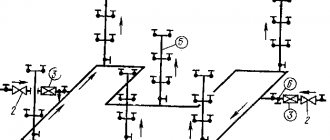
Typical connection diagrams.
It would seem - what a problem if there are detailed connection diagrams and even recommendations for connection.
Connection recommendations for valve control and a copy.
Having studied the above documentation, we come to the following diagrams for connecting a single-phase valve to a single-phase valve control cabinet.
Typical connection diagram to the control cabinet from the ShAK passport:
Control circuits from internal SHAC connection circuits:
Typical valve connection diagram from the valve data sheet:
Gate valve position microswitches:
1KVO/1KVZ Limit microswitches OPEN/CLOSED.
1VMO/1VMZ Clutch opening/closing microswitches.
2KVO/2KVZ Microswitches for position indicator OPEN/CLOSED.
The electric valve is supplied with non-adjusted cams for the actuation moment of microswitches 1KVO/1KVZ and 2KVO/2KVZ - their adjustment requires attention and patience.
From the connection diagram inside the valve, we see that the valve control circuit includes breakers - microswitches 1KVO/1KVZ and 1VMO/1VMZ , which stop the movement of the valve.
The 1KVO/1KVZ limit microswitches need to be configured and they interrupt the motor power supply circuit when the extreme positions are reached.
The 1VMO/1VMZ clutch switches are triggered by excessive force when the valve reaches the stop position, and this is how it is described in the valve data sheet:
The worm shaft of the power transmission is balanced on both sides by disc springs, which make it possible to ensure the permissible amount of torque developed by the electric drive.
Elements of a double-sided overload clutch allow you to automatically turn off the drive motor in emergency situations (if the torque exceeds the rated one).
Not all valve modifications have 1VMO/1VMZ - low-power valves often do not have them.
If you incorrectly set the microswitches 1KVO/1KVZ and 2KVO/2KVZ of a valve without coupling microswitches 1VMO/1VMZ , the valve motor may burn out.
From the ShAK connection diagram we see that input terminals 1-2,3-4 for connecting the valve limit switches are intended simply to disconnect the valve control circuits. But the break in the control circuit has already been implemented inside the valve.
Thus, it may seem (and maybe it is) that it is enough to simply connect the valve to the valve control output by shorting the input terminals 1-2,3-4 SHAC for the valve position limit switches with jumpers.
And connect the microswitches of the OPEN/CLOSED position indicator 2KVO/2KVZ to the signal loops of the control device of the Sprut-2 set for dispatching and signaling.
Indeed, it would not hurt to generate signals “Attention - the valve is open” and “Attention - the valve is not closed” - in case someone randomly opens the valve and leaves.
Electric drive device
The main components of electric drives of the GZ-G series are:
- cast body;
- handwheel handwheel attached to the body;
- flange;
- electric motor
Inside the housing there is a worm gearbox, an output shaft, a torque coupling, a valve position indicator, and a shaft travel length limiter.
There are options for electric GB drives in explosion-hazardous versions in accordance with the ExdIIBT4 standard. Devices with a degree of protection IP65 completely protect against dampness and dust. The transition from manual mode to process control mode from an electric drive for GZG models is carried out manually.
PKL line monitoring device.
The valve control circuits in the fire protection system must be monitored.
Sprut-2 equipment includes a special device for this - a line monitoring device.
The PCL is specially designed for use in ShAK and is intended to monitor the health of AC electric drive connection circuits.
PKL and ensures the implementation of the requirements of GOST 53325-2012: “7.4.1:
PPU must ensure the following functions:
c) automatic monitoring of the health of communication lines (for wired ones - for breaks and short circuits, for radio channels, fiber optic and digital communication lines - for loss of communication):
— with actuators of fire protection systems (sounders, information boards, electric valves, squibs, pumps, fans, electric motors, etc.);
Note – Monitoring the serviceability of communication lines with squibs and actuators of fire protection systems, powered by voltages above 150 V, can only be carried out for breaks.
PKL passport: PKL-16-04-18.pdf
When ordering ShAK or in the configurator, you must specify the PCL option:
Materials used
The quality and durability of the device depends on the material used to manufacture electrical shut-off valves. It also determines the future scope of application.
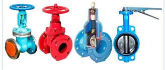
Valves are often produced that are made from:
- Stainless or galvanized steel.
- Bronze.
- Cast iron.
- Brass.
Each material has its pros and cons, but this does not affect the functioning of the device itself in a technological sense. In any case, the opening and closing of the valve will occur thanks to an electric drive. Conventional valves made of bronze or brass are very popular, while those with an electric drive are less common. Often, cast iron and steel products are purchased.
Peculiarities of using PCL in valve control circuits with reverse.
In ShAK the PKL is connected directly to the valve control output terminals.
If there is a weak control current through the gate motor windings to zero, the PKL considers that the gate control line is normal.
This is how the PCL is connected to the valve in the ShAK:
Particular attention should be paid to the fact that when the valve moves, the PKL line for controlling the corresponding direction of movement of the valve closes to zero, which eliminates the control of this line.
This controls only the winding of the valve motor, which is designed to move the valve in the opposite direction to the current direction.
That is, if the “Close” command is given to the valve (this is the case in standby mode), then only the integrity of the line for movement in the “Open” direction will be monitored.
The valve will reach its extreme position and will be stopped.
Depending on the two connection options, the following situation will result.
1. If the valve is stopped by the internal valve switch , then the ShAK will remain in the state of closing the valve. The relay for controlling the movement of the valve in the closing direction will remain activated and will close the PCL line to zero with its contacts.
And, despite the fact that the motor circuit will be broken inside the valve, the PCL will not register this break.
This is correct - why control the closing circuit of a closed valve.
2. If we interrupt the movement of the valve using signal limit switches connected to terminals 1-2,3-4 SHAK, then the motion control relay will turn off to interrupt the movement of the valve and thereby stop shorting the PCL control line to zero.
But the valve motor circuit will not be interrupted by either the 1KVO/1KVZ or 1VMO/1VMZ , and thus the PKL will continue to monitor the integrity of the entire valve control circuits.
Correct implementation of this operating logic requires careful adjustment of the operating order of the limit switches 1KVO/1KVZ and 2KVO/2KVZ .
Types of shut-off electrical valves
Electric shut-off valves have no restrictions on the cross-section of the pipeline. The connection is made using flanges.
Structurally, locking fittings are divided into:
- Disk. The overlapping membrane is made in the form of a disk, which is installed either perpendicularly or at any angle to the flow. These devices are very easy to maintain and inexpensive. An economical option is to use a combined type. Here the membrane is made of stainless steel, and all other metal elements are made of ordinary steel. Cannot be used on high pressure pipelines.
- Wedge (also called conical). The main element of the mechanism is a wedge placed on a retractable spindle. It is used to shut off pipes with a “clean” carrier, since the device quickly corrodes and breaks.
- Parallel. The valves have 2 seats with discs that are located parallel. There are gate and hose types.
Mechanisms are also distinguished by the location of the running element. There is a crane with a retractable and non-retractable spindle. Different designs affect the scope of application, as well as the capabilities of the valve.
The rising spindle has threads located outside the valve body. Therefore, sufficient space is required for installation. But the advantage of the design is that the external elements are protected from damage by the internal environment.
For the non-rising type, the threads are always located inside the valve body. Such a locking mechanism is quite easy to install in hard-to-reach places and small spaces. But if there is an aggressive environment in the pipeline, then the mechanism will be constantly exposed to its destructive effects. This will sooner or later lead to a breakdown, but repairs will be complicated due to the inaccessibility of the valve location.
Switching the ShAK to manual valve control mode.
From the connection diagram in the ShAK valve control circuits it can be seen that in the “Auto” The control circuits are always in the valve motion state. According to the automation signal, only the direction of movement of the valve changes using the KZZ : in standby mode, in the absence of a command, the valve closes; At the automatic command, the valve opens.
Thus, the PCL control line corresponding to the direction of movement of the valve is always closed to zero.
But what if the valve control in the ShAK is switched to the “Local” mode? ?
Control of the valve inside the ShAK will stop until a command is given by the buttons on the ShAK panel and neither of the two PKL control lines will be shorted to ground.
Thus, when the limit microswitches 1KVO/1KVZ the valve motor control circuits inside the valve and disable manual control, the PKL will register an accident “breakage of the valve drive control circuits.”
What to do?
You can ignore such an incident, which arises when three circumstances coincide: the ShAK is in manual control, the valve has reached its extreme position and manual control is turned off.
No, you can, of course, not order PKL as part of the ShAK at all or short the PKL control lines to ground, simulating the integrity of the valve motor winding - but this is not our method.
Operating principle of a valve equipped with an actuator
An electric drive valve operates on the well-known and simple principle of a rotary disk, the task of which is to contain the flow of water or other liquid in a timely and reliable manner.
Thus, the disk occupies a strictly perpendicular position relative to the flow axis, and does this after receiving the corresponding signal. In different configurations, options for equipping with a return spring are possible, but there are models without it. The working mechanism is located inside the housing; it consists of two (usually) saddles installed either parallel or at an angle relative to each other. For reliability, in the “closed” position there are special seals that provide additional sealing of the shutter.
The shutter itself also moves, only the movement itself is carried out by a rod or spindle (it differs in different models). The spindle, complete with a running nut, is nothing more than a threaded pair, the task of which is to carry out the working movement of the shutter itself in the required variants.
Connecting the valve to the ShAC with the exception of line integrity failure.
1 way.
The external stop of the valve movement upon reaching the extreme positions will still have to be carried out using specially designed ShAK inputs 1-2,3-4.
Microswitches of the position indicator 2KVO/2KVZ are connected to inputs 1-2,3-4 SHAK, as shown in the standard diagrams.
In this case, there will be no possibility of dispatching the state of the valve. There is no place to get these signals from - the ShAK does not generate logical states from inputs 1-2,3-4 of the end positions of the valve.
In addition, it is necessary to adjust the timing of the limit switches so that the 1KVO/1KVZ , which cause an emergency signal, are triggered later than the 2KVO/2KVZ , which stop the valve from moving.
Setting the microswitches again will not be easy.
But we also need to configure all these microswitches so that the valve does not allow water to pass through after the movement stops when the 2KVZ .
All this may not be feasible within the required period of adjustment work and may not work reliably.
An alternative is to ensure that the water is completely shut off and require the personnel to manually pull the valve to the closed state after each operation or testing of the fire extinguishing system.
Method 2.
The internal valve control circuits are assembled on the same terminal to which the external control and monitoring circuits are switched.
Therefore, it is possible to change the connection diagram in such a way as to separate the circuits of the OPEN/CLOSED 1KVO/1KVZ and the 1VMO/1VMZ (if the valve modification is without coupling microswitches, the circuits will already be disconnected).
The 1VMO/1VMZ coupling microswitches will remain in the valve motor power supply circuit and will act as emergency stroke interrupters: their operation will generate an “open circuit of the valve drive control circuit” alarm.
The limit microswitches OPEN/CLOSED 1KVO/1KVZ will be connected to the valve position control inputs 1-2,3-4 SHAK.
Microswitches of the position indicator OPEN/CLOSED 2KVO/2KVZ will be signal and connected to the control device loop to generate signals “Attention - the valve is not closed/open”.
Advantages and disadvantages
The advantages of valves with electric drive include:
- The ability to quickly regulate the flow of the working medium in the pipeline.
- Automatic control.
- Closing and opening the locking mechanism in the fittings of any DN without the use of physical effort.
- Remote control of the flow of the working medium, installation in places hard to reach for humans.
- Corrosion resistance.
- Resistance to hydraulic shocks.
- Easy to control via cabinet or remote control.
There are also disadvantages. For example, such fittings require an uninterrupted supply of electricity to function. There is a possibility of depressurization when using low-quality gaskets.
Specifications
When choosing a model, take into account the conditions in which it will be used (indoors, outdoors or under a canopy). If the marking contains the letter “U” and the numbers 1 or 2, the equipment is used at ambient temperatures from −40°C to +40°C. The designation “UHL” indicates the possibility of using the equipment at temperatures from −60°C to +40°C. In the southern regions, devices marked “T” are installed. They can operate at temperatures from −10°C to +50°C. Each climate version has a certain temperature reserve.
The diameter of the fittings is selected in accordance with the characteristics of the pipeline. The minimum value is 40 mm, and the maximum is 600 mm or more. For the smallest standard device, the maximum torque is 60 Nm, the rated current is 1.7 A. The largest unit has a maximum torque of 1000 Nm, and the rated current is 7.6 A. The table below shows the main characteristics of existing models:
| Name | Du | Housing material | Pn (RU) | Working environment | Price, thousand rubles |
| 30s541nzh | 300-1000 | Steel | 16 | Water steam, oil products, non-aggressive substances (gas, liquid) | 85-955 |
| 30s941nzh | 50-1000 | Steel | 16 | Water steam, oil products, non-aggressive substances (gas, liquid) | 4,2-890 |
| 30s564nzh | 300-1000 | Steel | 16 | Water steam, oil products, non-aggressive substances (gas, liquid) | 70-1044 |
| 30s964nzh | 50-1000 | Steel | 16 | Water steam, oil products, non-aggressive substances (gas, liquid) | 5,8-938 |
| 30s515nzh | 50-400 | Steel | 16 | Water steam, oil products, non-aggressive substances (gas, liquid) | 5,5-104 |
| 30s999nzh | 50-250 | Steel | 25 | Water steam, oil products, non-aggressive substances (gas, liquid) | 6,3-37,9 |
| 30s915nzh | 50-400 | Steel | 40 | Water steam, oil products, non-aggressive substances (gas, liquid) | 6-200 |
| 30s576nzh | 50-400 | Steel | 63 | Water steam, oil products, non-aggressive substances (gas, liquid) | 11-279 |
| 30s976nzh | 50-400 | Steel | 63 | Water steam, oil products, non-aggressive substances (gas, liquid) | 9,6-355 |
| 30h906br | 50-400 | Cast iron | 10 | Water steam, gaseous media, petroleum products | 2,8-23,5 |
| 30h915br | 50-1400 | Cast iron | 10 | Water steam | 148-1597 |
| 30h925br | 50-1600 | Cast iron | 2,5 | Water steam | 132,5-2211 |
| 31h917bk | 50-400 | Cast iron | 10 | Water steam | 4,6-70 |
| 30ls964nzh | 50-400 | Alloyed | 25 | Water steam, oil products, non-aggressive substances (gas, liquid) | 6,8-189 |
| 30ls915nzh | 50-400 | Alloyed | 40 | Water steam, oil products, non-aggressive substances (gas, liquid) | 8,5-373 |
| 30ls976nzh | 50-400 | Alloyed | 63 | Water steam, oil products, non-aggressive substances (gas, liquid) | 13-405 |
| 30ls941nzh | 50-1200 | Alloyed | 16 | Water steam, oil products, non-aggressive substances (gas, liquid) | 6,5-457 |
| 30nzh941nzh | 50-500 | Stainless steel | 16 | Water steam, petroleum products, aggressive substances, acids | 18-833 |
| 30nzh915nzh | 50-600 | Stainless steel | 40 | Water steam, petroleum products, aggressive substances, acids | 23,2-1778 |
| 30nzh976nzh | 50-500 | Stainless steel | 64 | Water steam, petroleum products, aggressive substances, acids | 33-1151 |
Gates
This device is more functional. It closes and regulates the flow.
Applicable for large diameter pipelines.
The most common option is a butterfly valve.
To control the position of the valves, a position device for butterfly valves is provided.
The cross-sectional diameter of the pipe corresponds to the diameter of the disk.
Rotary locking mechanism, controlled manually from the handle or remotely through the control panel (at high pressure).
If the pressure in the fire extinguishing system is too high, the device is not applicable.
A good company specializing in the production of valves of this and other types is ARmatek CJSC.
This type of fittings is widely used.
- Heat supply.
- Water supply.
- Gas supply and ventilation.
- Firefighting.
- Special conditions: delivery of fuels and lubricants, etc.
Why do we distinguish gates from other types of electrical fittings? They are distinctive in that:
- during repairs we can quickly replace the main components;
- have low weight, dimensions and simple internal design.
- they can be used in large diameter pipelines.
We consider the disadvantage that in the “open” state, the disk closes part of the hole and reduces the throughput.
You also have to apply a lot of force to the handle due to the low torque of the design.
We classify the shutters as follows.
- The locking element is lens surfaces or a flat disk.
- The material used is cast iron and steel.
- The inside can be finished with rubber liners or have no finishing.
- Different diametrical size of the passage hole.
The control is similar to a ball valve. Some bolts have a handwheel or gearbox to increase the force applied to the handle.
Installation features
Installation of electrical fittings is often carried out only by qualified teams. Before starting the installation, the device must be decondensed, excess lubricant must be removed, plugs must be removed and performance checked. All technical parameters specified in the product passport must fully comply with the pipeline data.
Installation can be performed in both vertical and horizontal positions. It is not recommended to install the valve upside down, as dirt will collect near the rod, and this will gradually lead to jamming of the spindle. Valves with an electric drive with a diameter of more than 10 cm must be equipped with an additional fixed support.
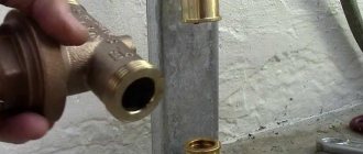
Connecting the device to pipelines directly depends on the material from which it is made. For example, a cast iron valve is connected using flanges. To do this, you will have to weld the same abstract elements to the ends of the pipes. This connection, thanks to bolts and a rubber gasket, ensures high tightness. Welding defects cannot be compensated for by adding additional seals.
After installation is completed, assembly of the mechanism control unit begins. It includes elements of automation, as well as a power unit. The first ones send a signal from the button to the drive. The power part is located in an electrical cabinet installed near the valve. The last step will be to check all types of controls.
Hydraulic tests are performed on the connected structure. Defects found cannot be eliminated by tightening bolts. Installation can only be considered complete after all checks have been carried out.