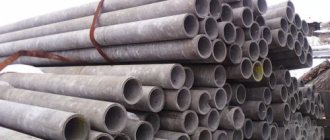
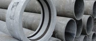
Good to know: PVC pipes for sewerage GOST 51613 2000 are non-pressure, for internal and external systems (polyethylene elements). In this article we will consider: regulatory documents, requirements, advantages, characteristics. First things first.
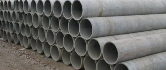
When creating a sewerage project, the main task is the correct selection of pipelines. The best choice is considered to be PVC pipes for sewerage according to GOST 51613-2000, free-flow or for forced pumping under pressure. They have wide capabilities and can be used in different systems and conditions. Unlike previously used cast iron or asbestos cement types, plastic products are superior in weight, ease of assembly and other aspects. Let's take a closer look at them.
Specifications
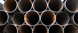
PVC sewer pipes GOST 51613 are products made from ordinary (PVC) or unplasticized (UPVC) polyvinyl chloride. They are intended for use in pressure or non-pressure networks of internal and external lines. Plastic pipes have a smooth inner surface that prevents the formation of layers or blockages.
Performance qualities demonstrated by sewer pipes GOST 51613-2000 (or another valid for plastic products):
- resistance to most alkalis, acids or oils;
- do not burn under normal conditions;
- retain their original hardness at temperatures up to 65°;
- the melting temperature of the material is 150°-220°;
- dielectric material prevents the appearance of stray currents.
When choosing PVC pipes and fittings for sewerage according to GOST 51613, it is necessary to take into account that they are designed to move wastewater with temperatures up to 45° (short-term work with liquids at 80° is allowed). Therefore, they cannot be used for constant transportation of hot water. Most sewer networks operate with cooled wastewater, so they are not required to withstand high temperatures. However, there are special chlorinated PVC pipes for sewerage according to GOST 51613, which are capable of working with liquids up to 95°. They can be used for assembling industrial sewerage, as well as for supplying hot water.
Polyethylene sewer pipes for external sewerage GOST 22689.2-89 have similar properties. They tolerate temperatures up to 65°, which is quite enough for underground parts of the sewer system. PVC and polyethylene pipes can be used in one line; only connecting adapters are needed. The length of straight sections ranges from 4 to 12 m, and the permissible deviation is 25 mm in both directions.
Ukraine
In Ukraine, there is only one standard for pipe products made of uPVC - DSTU B V.2.5-322 007. The difference is that the Ukrainian document regulates the requirements for non-pressure products. Its dimensions should be six meters long. Deviation of up to one tenth of a meter is allowed. By agreement with the consumer, it is possible to manufacture products of other lengths.
The purpose of the product is the installation and repair of pipelines with a maximum operating pressure of up to 0.16 MPa for the purpose of water disposal and the creation of sewer systems, as well as the laying of communication cables. The temperature range can be from zero to forty-five degrees. In addition, short-term transportation of liquids with temperatures up to ninety-five degrees is allowed. The maximum use time under these conditions is one minute.
DSTU B V.2.5-322 007 (unlike the Russian analogue) also contains requirements regarding corrugated products and fittings. Both standards contain detailed information on all technical requirements for PVC components. The documents contain all the data regarding its characteristics. Particular attention should be paid to data regarding dimensions, permissible pressure, temperature conditions, installation, marking and transportation.
Regulatory documents and requirements
The main document regulating the production of PVC sewer pipes is GOST 51613-2000. It only applies to uPVC (PVC) products and does not apply to gas pipelines. Electrical installation channels, for which there are specific standards, are also not regulated.
GOST requirements concern the main parameters:
- outer and inner diameter;
- Wall thickness;
- surface quality;
- absence of defects (bubbles, mechanical damage, chips).
PVC pipes for internal sewerage according to GOST 51613 belong to hazard class 3. The ignition temperature of the material is 300°. The recommended area of use is the transportation of wastewater at temperatures of 0-45° in gravity or pressure networks. It is possible to work with liquids or gases other than aggressive or flammable compounds. The permissible change in dimensions when the material is heated is no more than 5%. This is an important indicator, since sewage drains have different temperatures. Sudden changes can cause destruction of connections, which is unacceptable for external areas.
Other types of PVC pipes for drainage
The latest polymer product to enter the market is corrugated PVC pipe for sewerage. It is manufactured according to GOST R 54475-2011. Corrugation, or structured wall, can be circular, spiral and longitudinal, with hollow and solid ribs (sections), with smooth outer and inner surfaces (type A), with a corrugated top (type B).
Corrugated pipes are intended for non-pressure external sewerage networks. Their range includes pipes of the DN/ID series with a diameter of 100 – 2,400 mm and DN/OD – 110 – 1,200 mm. The range of pipes includes products of classes SN 2, SN 4, SN 8 and SN 16. Products of the heaviest class allow the installation of sewerage at a depth of up to 50 m underground. The corrugation enhances the pipes’ resistance to transporting liquids heated to 79 °C.
If you have any questions, call the toll-free number
8-800-250-4337 or you can request a call
and our managers will contact you.
Request a call
Types of sewer pipes GOST 51613-2000
There are several types of PVC sewer elements:
- pressure;
- non-pressure;
- for internal sections of the system;
- for external parts.
Piping for internal parts is grey. They are available in three types:
- socket-type, designed for adhesive joints (RC);
- straight, without socket, intended for coupling connection;
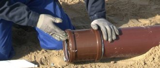
- socket-shaped for a rubber ring or other seal.
PVC-U pipes for external sewerage according to GOST 51613 differ from internal ones in their orange color and increased wall thickness. Otherwise, they are the same products, having three types of connections. For replacement, polyethylene pipes for external sewerage GOST 22689.2-89 can be used. They
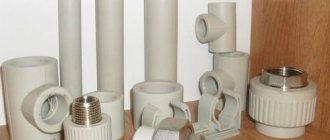
In addition to the straight sections that make up the main part of the sewerage system, shaped products or fittings are produced. They are fully compatible with direct components and are made from the same material. Used to change the direction and diameter of the channel, branching or connecting lines to the main pipeline. All parameters, characteristics and capabilities of fittings completely coincide with the properties of straight pipelines. The difference is only in the form and purpose of the elements.
You may also like:
GOST water supply and sewerage internal networks
Fittings for sewer pipes: sizes, types, characteristics
Fittings for drainage networks made of PVC pipes
To install drainage systems, in addition to pipes, fittings are required to assemble individual elements into a single network. The range of shaped products is presented in GOST 32412-2013 and GOST 32413-2013. It includes:
- bends with bend angles of 15, 30, 45, 67.5 and 87.5–90 degrees; the range of bends to internal networks additionally includes products with an angle of 22.5°;
- sliding and socket couplings;
- adapters from larger to smaller diameter pipes;
- regular and transition type tees with third side connection angles of 45, 67.5 and 87.5–90 degrees;
- saddle bends and plugs for external sewerage pipes.
Shaped parts are manufactured for socket and push-in connections, including in various combinations. For example, an external PVC sewer pipe with a diameter of 200 mm of the socket type can be connected to a straight product, including a larger or smaller one. The marking of fittings indicates their main characteristics:
- for a conventional tee – nominal diameter and connection angle;
- for adapters and transition-type tees - all connecting dimensions and connection angle;
- for shaped products to external networks, the pipe class designation is added to the marking, for example SDR 41, as well as the name of the part (coupling, tee, etc.).
The methods of applying markings to pipes and fittings for them are identical - relief embossing or printing with indelible paint. A certificate for PVC sewer pipes confirms that they are made from raw materials of appropriate quality and have been tested upon acceptance for tightness, impact strength and other parameters.
Advantages and disadvantages
The advantages of PVC pipes include:
- relatively low price;
- lack of reaction to ultraviolet light;
- smooth surface of the internal walls, preventing the formation of blockages;
- impossibility of corrosion;
- long service life (according to manufacturers, up to 50 years);
- mechanical strength of the pipes themselves and connecting elements;
- high assembly speed;
- light weight, ease of loading, transportation and storage;
The disadvantages of PVC pipes include:
- the material becomes brittle as the temperature drops. If assembly is carried out in the cold season, this point must be taken into account and act carefully;
- low sound insulation;
- inability to work with hot liquids;
- freezing of water in the cavity of the system leads to its destruction.
Another disadvantage is the high temperature expansion of the material. A socket assembly with a seal, which uses a rubber ring or special packing, allows compensation for changes in dimensions. An alternative option is polyethylene sewer pipes GOST 22689.2-89, which have lower thermal expansion.
Questions GOST R 54475–2011 “Polymer pipes (...) for external sewerage systems”
State Unitary Enterprise "NIIMosstroy", on the instructions of the Russian Committee on Science and Technology, carried out relevant research and developed standards [1-4] for the use of pipes similar to those given in the standard (Fig. 1e), which allows, in accordance with these standards, to install wastewater pipelines in Moscow already more than 10 years [5-9]. From the name of the standards [TR 170-05 “Technical recommendations for the design and construction of drainage networks from free-flow polyethylene pipes with a two-layer wall” (internal diameter of pipes 100-450 mm) and TR 171-05 “Technical recommendations for the design and construction of drainage networks from free-flow polypropylene pipes with a two-layer wall" (outer diameters of pipes 160-630 mm)] it can be seen that the pipes are called differently - “free-pressure polyethylene pipes with a two-layer wall...” and “free-pressure polypropylene pipes with a two-layer wall.”.
There is an acute problem associated with the improvement of GOST and consists in taking into account the accumulated experience when developing new standards
In this regard, an acute problem arises, which we associate with the improvement of GOST and which consists in taking into account the accumulated experience when developing new standards, for example, standards for organizing service stations - after all, today in the country there are similar pipes with a diameter of up to 2.5 m on the market, both domestic and foreign manufacturers.
1. As the name suggests, the standard should apply to pipe products made of polymers. We cannot fully agree with this. After all, the concept of polymers includes many different types (Table 1).
2. Section 1 of the standard “Scope of application” indicates the materials from which pipes with a structured wall should be made (Table 2).
These are PE (polyethylene), PP (polypropylene) and UPVC (unplasticized polyvinyl chloride), which are thermoplastics. Thermoplastic materials or thermoplastics include polymers that, when heated during processing, transform from a solid state of aggregation into a liquid - highly elastic or viscous-flow state (molded thermoplastics pass into a viscous-flow state). When the material cools, a reverse transition to the solid state occurs.
The behavior when heated distinguishes thermoplastics from thermosets or thermosets, which harden during processing and are not able to further transform into a liquid state. Obviously, based on this, in the name of the standard, instead of the concept of “polymer”, the concept of “thermoplastics” could be used. It would seem that the name of GOST should have been changed to “Pipes with a structured wall made of thermoplastics and fittings for them for external sewerage systems.” However, this will also be inaccurate, since, in addition to the indicated thermoplastics (PE, PP and PVC-U), there are also other types (Table 3).
Unfortunately, it is not known whether it is possible to produce economical pipes with a structured wall from other (Table 2) thermoplastics, to which the requirements of the standard in question could be extended. In this regard, it seems that in GOST it would be advisable to replace the concept of “polymer” with “PE (PE), PP (PP) and PVC-HD (PVC-HD)” and its name would become: “Pipes with a structured wall made of PE ( PE), PP (PP) and PVC-U (PVC-HD) and fittings for them for external sewerage systems.”
But this will also be quite inaccurate. For among pipe polyethylene there are brands PE-32, PE-63, PE-80 and PE-100, polypropylenes - PP-H, PP-B, PP-RC and PP-RCT, unplasticized polyvinyl chlorides - UPVC-60, UPVC-100 and NPVH-125, which are significant for pipe products, the indicators of which (manufacturability, strength and cost-effectiveness) differ significantly. In this regard, the omission of the authors of GOST should be considered that GOST does not contain indicators of the properties of these thermoplastics, such as: initial strength and elastic modulus, deformability, melt flow index (MFR - for polyolefins), etc. It seems that this gap should be filled in the new edition of GOST.
The wastewater disposal system is a complex of internal sewerage (with outlet), sewer networks, pumping stations designed for collecting and discharging wastewater from individual users or their aggregate, as well as wastewater treatment and disinfection facilities
Storm sewer is a sewer system that provides collection and disposal of atmospheric wastewater, as well as water from street irrigation outside populated areas and industrial enterprises [10]. It is impossible to fully agree with such a set of terms, because the use of terms that are synonyms of a standardized term is prohibited (see GOST 25150-82 “Sewerage. Terms and definitions”). This clearly requires clarification.
3. The title of the standard states: “...for external sewerage systems”, and in section 1 of the standard “Scope of application” - “... for non-pressure underground external sewerage systems: domestic sewerage, drainage and water disposal, storm sewerage, industrial wastewater disposal...”. “Sewage system”, according to the Code of Rules 32.13330.2012 “Sewerage. External networks and structures. Updated version of SNiP 2.04.0385” is “a set of interconnected structures designed for collecting, transporting, treating wastewater of various origins and discharging treated wastewater into a receiving reservoir or for supply to recycling water supply facilities. Includes sewer networks (including snow melting points and drainage stations), pumping stations, regulating and emergency regulating reservoirs, and treatment facilities. It is divided into all-alloy, semi-separate and separate. " Sewer network, according to TSN EK-97 MO “Territorial building standards. Technical rules and regulations for the construction, operation and control of the operation of drainage system structures for low-rise buildings on the territory of the Moscow region" is "a system of underground, above-ground and above-ground pipelines and structures on them for the collection and disposal of wastewater.", and the drainage system is a complex of internal sewerage (with outlet), sewer networks, pumping stations designed to collect and discharge wastewater from individual users or their aggregate, as well as facilities for the treatment and disinfection of wastewater before discharge into a receiving water body. A pipeline is “a structure made of pipes tightly connected to each other...” [10]. Drainage is “draining the soil by. pipes, as well as a system of such... pipes” [10]. Water disposal, according to the Federal Law of December 7, 2011 No. 416-FZ (as amended on July 21, 2014) “On Water Supply and Water Disposal,” is the reception, transportation and treatment of wastewater using a centralized drainage system.
4. Pipes with a structured wall (Fig. 1f) are used [11] in the construction of telephone sewerage pipelines (“special sewerage system for laying telephone cables underground, constructed from pipes in special trenches at a depth of 0.6 to 1.1 m...” [10]). Various inspection wells are made from pipes with a structured wall (Fig. 1c, e of the original), for example, according to TU 2291007073011750-2010 using extrusion welding based on parts of Korsis / Korsis Plus pipes, water tanks (Fig. 2), septic tanks and other products [9], which also needs to be taken into account in the next edition of GOST.
5. Section 3, paragraph 3.1, provides the term/definition - “structured wall pipes and fittings.. However, the standard contains virtually no information about structured wall fittings. The main emphasis in it is on shaped parts with a solid wall, manufactured by injection molding. In fact, structured wall fittings are indeed produced, but they are made from sections of the same pipes (Fig. 1e of the original) using welding.
In this regard, it is quite obvious that the standard should reflect the requirements for the above-mentioned products. Here it also seems that the most suitable wording for the name GOST would be:
“Pressure-free pipes with a structured wall made of PE, PP and PVC-HD and products for them. Technical conditions".
6. An adjustment should also be made to paragraph 4.3.2 [“for the DN/OD series, the dimensions ensuring connection with pipelines, the classification of which is carried out according to the nominal outer diameters dn established by GOST ISO 11922-1, must correspond to table. 2 (here table 4) and for the DN/OD series, dimensions that do not provide connection with pipelines, the classification of which is carried out according to the nominal outer diameters dn established by GOST ISO 11922-1, must correspond to table. 3 (here table 5)..."].
Here we cannot agree with the reference to GOST ISO 11922-1, although those available in table. 4 digits can be considered satisfactory. It states that “the standard establishes tolerance grades for the outer diameter, ovality and wall thickness of metric series pipes made of thermoplastics for transporting liquid and gaseous media, manufactured with a nominal outer diameter and a nominal pressure in accordance with ISO 161-1 and a nominal thickness walls in accordance with ISO 4065, applies to smooth pipes made of thermoplastics of round and constant cross-section along the entire length, regardless of the method of their manufacture, the material used and the purpose ... ". It is impossible to agree with the use of the term “not providing” here (Table 5), since the figures given in this table for the average internal diameters of the sockets are quite acceptable so that it would be possible to qualitatively assemble pipe connections with those indicated in the table. 5 average outer diameters among themselves without their selective selection during construction, even with the use of tension or any other mechanisms.
7. There is no clarity in paragraph 3.1 “Pipes and fittings with a structured wall”: “Products having a wall structure optimized in terms of material consumption that meets the requirements of this standard...”. How to understand “optimized” is “a decrease or increase in the material used for the manufacture of pipe products. "or adjustment to pipe geometry (see Fig. 1 in GOST)? Or did the authors mean to correlate their masses with ring rigidities? Then it should be written: “minimized.” However, this will not be entirely accurate. Because one should also take into account the throughput of pipes, which is directly related to their internal diameters.
8. The advisability of using a combination of the terms “underground” and “external” in the standard also raises doubts. If we keep in mind that the underground pipeline can be internal, for example, laid in the ground under the building or outside the building (sewage outlet), then in this case the specified combination may occur. True, this prevents the possibility of constructing these pipelines from pipes with a structured wall, which is unacceptable from both a technical and economic point of view.
Underground pipelines can also be located in channels, tunnels, sewers, for example, in permafrost conditions. In these cases, the pipelines will naturally be classified as external. In the context of the GOST under consideration, it would be more accurate to indicate: “a pipeline laid directly in the ground...”.
9. GOST establishes requirements for the values of ring stiffness, paragraph 4.2.1: “The nominal ring stiffness of pipes and fittings must be selected from the following range: for DN500 - SN4, SN8 or SN16; for DN > 500 - SN2, SN4, SN8 or SN16. For DN500, it is allowed to use for design calculations the minimum ring stiffness value guaranteed by the manufacturer, which is between the specified nominal values SN. In this case, pipes must be designated and marked with the nearest lower class SN. " Strictly speaking, this requirement forces pipes on the market with ring stiffnesses of, for example, 12 kPa to be classified as SN8. We cannot agree with this. After all, it is the ring rigidity that largely determines the cost-effectiveness of installing such pipelines and subsequent reliable service in water disposal networks (sewerage and drains) for the entire estimated forecast period - as a rule, at least 50 years. Depending on the accepted ring rigidity for the specified pipes, soils with the required characteristics and excavation technology (compaction of selected soils around laid pipelines) are then adopted.
Research by the State Unitary Enterprise "NIIMosstroy" [12], carried out on pipes with a smooth solid wall, showed that the main parameter determining the reliability of the functioning of underground free-flow pipelines made of pipes made of thermoplastics (namely, the relative shortening φ of the vertical diameter of their cross section) is associated with their initial cylindrical stiffness Go [MPa] (in GOST - SN [kPa]) by the following inversely proportional relationship
where φ is the relative shortening of the vertical diameter of the cross-section of the pipe under the influence of soil and transport loads; q is the total pressure on pipes of soil, transport and other temporary and permanent surface loads:
where k1, k2 and k3 are coefficients; E0 is the initial tensile modulus of elasticity of the pipe material, MPa; Er is the initial modulus of soil deformation in the trench cavities, MPa; SDR - pipe dimensional ratio (ratio of outer diameter D to wall thickness e [m]);
where μ and β are coefficients taking into account the lateral resistance of the soil and the angle of support of the pipe on the bed; μ—Poisson’s ratio of the pipe material; k3 = 1 (soil without compaction) and k3 = 0 (with compaction to a degree greater than 0.96). As a result, it will turn out that the resource of pipes with SN12, which according to this GOST were “transferred” to the SN8 series, will be underutilized by approximately one third!
10. From the standard (Section 4) it is advisable to remove everything that concerns pipes with longitudinal hollow sections (Fig. 1b, in the original - type A1) and with annular ribs and a solid profile (Fig. 1b, in the original - type B), as not found applications.
11. The standard places too much emphasis on impact testing of tubular products. Such tests were used in practice, in the context of the standard, only for small diameter pipes (110-200 mm). In addition, as our practice of using pipes made from the most fragile thermoplastic PVC-U in Moscow construction shows, they were indeed subjected to such tests at the initial stage (1980s). Sometimes negative results were obtained. As for pipes made of PE and PP, no negative results were observed. Later, as experience with polymer pipes accumulated, this test was no longer used. Taking into account the fact that mainly pipes with annular or spiral hollow sections (Fig. 1c, in the original - type A2), with a spiral or annular hollow profile (Fig. 1e, in the original - type B) and with ring hollow profile (Fig. 1e, originally type B), and, as a rule, made of PE and PP, the impact test can be safely excluded.
12. Instead of indicating in GOST that “The design and dimensions of the wall are given in the design and technical documentation for the product. ", it is advisable to provide the basic requirements for pipes with a structured wall and use a different wording: "The design and dimensions of the wall must be technically and economically justified and given in the relevant sections of the documentation for this pipe product."
13. It is difficult to agree with section 4.3.3 “Connections of pipes and fittings” regarding socket joints of pipes with a structured wall (Fig. 2 in the standard, here – Fig. 3), where in one case (Fig. 3a) the symbol e2 indicates the wall thickness the cylindrical part of the bell, and in the other (Fig. 3b) - the same symbol indicates the distance between the outer surfaces of the bell on one pipe and the smooth end on the other pipe. Here, in the first case, the symbol e3 actually indicates the thickness of the wall of the groove for the sealing ring. In the second case, the groove and the ring are located on opposite sides of the wall of the second stage of the bell, because the figure shows a two-stage bell, and the symbol e3 indicates the thickness of the wall of the second stage, and not the groove.
14. As for all socket joints with rubber O-rings, first of all we should talk about the depth of the sockets - the distances between their ends and the internal shelves (the shelf is the wall of the product between the wall of the socket and the body of the pipe), as well as the correspondence of their elements to each other - the dimensions of the outer diameter of the smooth end and the inner diameter of the socket, the outer and inner diameter, as well as the width of the ring, taking into account its cross-section and rubber hardness, as well as the permissible assembly forces for a particular type and size of connection. At the same time, for sockets with grooves (grooves is a term well-established in the literature and standards) (Fig. 3a, e), the distances from the edge of the groove to the end of the socket and full compliance of its dimensions with the dimensions of the rubber sealing ring intended for use are important.
As for all socket joints with rubber O-rings, first of all we should talk about the depth of the sockets - the distances between their ends and the internal flanges, as well as the correspondence of their elements to each other and the permissible forces of assembling the connection
15. We cannot agree with the requirement: “If the sealing ring is installed at the pipe end of pipes and fittings (Fig. 2c, d in the standard, and in this article - Fig. 3c, d), the contact length must correspond to the table. 4, and the minimum length of the pipe end is determined by the formula Lim;n = Am;n + F, where Am;n is the contact length, that is, the length of the maximum possible separation of the pipe end and the socket, which ensures tightness; F is the distance from the pipe end to the point of effective compaction.”
According to the current terminology, instead of “pipe” the term “smooth” should be used, or, as is customary in GOST R ISO 2531 for ductile iron pipes, the “sleeve” end of the pipe (fitting). There should be no contact between the inner surface of the socket of one pipe and the outer surface of the smooth end of the other pipe. It is unclear what an “effective seal” is (here it is unnecessary) if it is required that “The installation position of the sealing ring at the pipe end must be indicated in the design and technical documentation for the product...” - after all, socket connections with rubber rings of pipe products are manufactured with dimensions , which should ensure waterproof connections. Here it is advisable to use the following phrase: “the depth of insertion of the smooth end of one pipe into the socket of another must correspond to the values specified in the design/technical documentation for the product or given in the table. ???".
The data (Table 4 GOST) also raises serious doubts. After all, the depth of the socket must take into account possible metamorphoses that can occur with socket joints located in the ground - mutual axial movements of connected pipes (during temperature deformations), uneven displacements in the vertical plane (during soil settlement), rotation in the socket relative to each other (during movements soils), different degrees of ovalization of the socket and the smooth end (under the influence of possible soil, transport and surface loads).
The determining factor here will be the temperature shortening/lengthening of the pipes, and they practically do not depend on the diameters of the pipes, especially if we take into account the pinching of pipes (with a structured wall) by the surrounding soil, which for pipes with a developed outer surface will occur in almost 100% of cases.
16. It is also impossible to agree with the following requirement: “The design and dimensions of adhesive and welded pipe joints must comply with the design and technical documentation directly from the manufacturer...”.
It is advisable to indicate at the beginning of paragraph 4.3.3 that the following connections can be used to assemble pipes with a structured wall: with rubber seals, welded (extrusion, ZN and heating tool butt welding), adhesive ("socket"). And in this regard, it would be more appropriate to provide the main provisions that ensure the quality, strength and cost-effectiveness of such connections on pipes with a structured wall. And even this will not be enough. Indeed, to assemble spirally wound pipes from a hollow rectangular (square) profile (Fig. 1c), mechanical “quasi-screw” connections are used, sealed with sealants and bandages (with pins and heat-shrinkable cuffs).
Naturally, all connections, regardless of design, must comply with the requirements specified in the accompanying documentation of manufacturers of pipe products with structured and other types of walls.
17. It is impossible to fully recognize the validity of the formula (4) presented here, discussed in this article, GOST (clause 4.3.5):
where Sso, Ssp and [SN] are the stiffnesses: the annular socket on one pipe, the pipe end on the other pipe, the nominal pipe.
From Fig. 2c, d it is clear that the “pipe ends” are a continuation of the body of the pipes without any changes, and in this regard they have the same ring stiffness Ssp as that of the pipe as a whole [SN].
According to (4), Sso can be equal to zero (sometimes this can happen, for example, when used in the assembly of heat-shrinkable cuffs). In this regard, the requirements for the wall thickness of sockets in such connections should not be determined by their annular rigidities. Most likely, they should be associated with contact pressures imposed on the walls of the sockets, compressed with seals (in GOST - rubber rings) in the cavity between the corrugations of the smooth ends, or assigned for design reasons, for example, taking into account manipulations during transportation or installation.
As for adhesive fittings, in the context of GOST under consideration, such products (except for saddle bends for smooth-walled PVC-U pipes, which are not manufactured using gluing, but can only be glued [13] onto such pipes) do not exist. The production of shaped parts by rotational molding is still, so to speak, “undeveloped virgin soil” for our conditions.
18. In the requirement of paragraph 4.3.5: “For sockets with an annular stiffness equal to or more than 4 kN/m, the minimum thickness of walls must correspond to table. 1. For sockets with a ring stiffness of less than 4 kN/m, the thickness of the inner layer should be 1.5 of that specified in the table. 1...” we cannot agree with the indicated values of the ring stiffnesses. After all, pipes are not made on sockets, but, on the contrary, sockets are molded, welded or glued onto pipes. It should be stated as follows: “the ring stiffness of sockets for assembling tubular products with wall thicknesses e4 and e5 (Table 1) should be no less than ??? (this should be established somehow, and not assigned a priori).”
19. In paragraph 4.3.6 “Wall thickness of shaped parts...”, along with “prefabricated welded” shaped parts (for example, Fig. 1a), “adhesive” as well as “manufactured by rotational molding” are mentioned. As for adhesive fittings, in the context of GOST under consideration, such products (except for saddle bends for smooth-walled PVC-U pipes, which are not manufactured using gluing, but can only be glued [13] onto such pipes) do not exist.
The production of shaped parts by rotational molding is still “undeveloped virgin soil” for our conditions. It is not entirely appropriate to include the term “rotation molding” at this stage of development of such technology in the country in the all-Russian standard (GOST). It should be noted here that in the Russian Federation there are several rotary installations up to 4 m high, on which elements of wells, tanks and tanks for antiseptics are molded, however, these installations are foreign, and the raw materials (special grades of polyethylene) for them are also supplied from milestone.
20. Clause 4.3.7 requires filling, given the claims of the authors (clause 4.3.6) to establish the wall thicknesses of fittings manufactured in various ways. Its saturation with decoding of symbols of pipe products is clearly insufficient for a standard (GOST) of this level. It would be necessary to supplement it with parameters, for example, related to extrusion welding, welding of NI segments cut from pipes with a structured wall, etc., when obtaining the same bends, tees and other products (Fig. 3 and 4) .
21. The wording in paragraph 8.4: “The determination of the ring stiffness of pipes is carried out on a testing machine capable of providing compressive deformation of the cross-section of a pipe sample installed between horizontal plates at a constant speed in accordance with Table. 22..." it is advisable [14] to be presented in the following form: "Ring stiffness should be determined by deforming a section of pipe at a constant speed (Table 22) with plates placed on different sides parallel to its longitudinal axis so that the compression force passes through the center of gravity of the section" . And taking this into account, make adjustments to the text of paragraph 8.4.
22. In paragraph 8.12, the requirement “The strength and flexibility of fittings is checked in accordance with Fig. 4 - . the shaped product is rigidly fixed to allow the application of a load that causes a displacement deformation A and a moment of force M..." should be excluded, since the values of A and M are not indicated. As follows from this fig. 4, casting bell-shaped fittings with solid smooth walls of small diameter are tested. This test method is not justified anywhere in the literature. It is hardly advisable to “fence a garden” for carrying out such tests on fittings made from pipe segments with a structured wall using extrusion welding or NI welding. Moreover, this is especially obvious when considering products of large diameters.
23. Clause 8.15 “The tightness of pipe connections using O-rings under internal hydrostatic pressure and internal reduced pressure is checked by deformation of the cross section of the pipe and socket and displacement of the longitudinal axes of the pipe and socket in accordance with Fig. 5..." it would be more expedient to present it in the following formulation: "the water tightness of socket connections with rubber sealing rings of pipes with structured walls between each other and with shaped connecting parts should be checked according to the "scheme with unloaded ends (Fig. 5 in GOST, here - Fig. 4 ) both internal pressure and external pressure - by creating a vacuum, and in both test options, at the same time, the connection elements (the socket of one pipe and the smooth end of the other pipe) must be subjected to compression and rotation relative to each other.”
The test design is not entirely accurate [15]. The forces F1 and F2 should be directed only downwards (this will load the connection with soil and transport), and not as shown in the diagram (from both sides). In the diagram presented here, the contact pressure of the rubber seal will decrease both at the bottom and at the top of the connection, but in fact there should be a decrease in the contact pressure at the top of the socket, and at the bottom of it, on the contrary, there should be an increase. In addition, the diagram does not take into account the mutual longitudinal movements of the connected elements, for example, during temperature changes. However, at this stage of development of the problem, it is possible to continue “further in the text”, taking into account the fact that the decoding of the symbols placed there does not always correspond to Fig. 5 in the standard (see here the designations for Fig. 4).
24. As for the information given in the reference Appendix B “Scope of application of pipes and fittings”, they do not stand up to criticism at all.
Indication here of some mythical areas of application of “U” and “UD” with reference to the European standard EN 134761:2007 “Plastics pipelines for free-flow underground sewerage and drainage systems - pipelines with a structured wall of unplasticized polyvinyl chloride (PVC-U), polypropylene (PP) and polyethylene (PE) - Part 1: General requirements and performance characteristics" [16] not only does not carry any useful information, it will create an obstacle to the widespread use of pipe products with structured walls, since hardly anyone will ever look into said EN.
The decision about which pipes from those used in general, including those considered here, should be used for the construction of a particular underground free-flow pipeline in specific soil conditions should be made on the basis of minimizing costs for its entire life cycle (life cycle consists of: production tubular products → pipeline design → its installation → operation → repair → disposal).
The decision about which pipes from those used in general, including those considered here, should be used for the construction of a particular underground free-flow pipeline in specific soil conditions should be made on the basis of minimizing costs for its entire life cycle (LC)
The question of how this should be implemented in practice [17], taking into account the requirements of the improved GOST R 54475, is currently being resolved by specialists from OJSC NIIMosstroy. This can be considered in more detail, if the wider scientific and technical community is interested, in future issues of the journal.
Specifics of external and internal pipelines
The components of the internal sections of the system are gray in color. Their diameter ranges from 25 to 200 mm, but the most common are 50 and 110 mm. As a rule, all straight sections and fittings have a socket type connection for a rubber ring. This is the most convenient installation method, allowing you to quickly disassemble and redo the work if necessary.
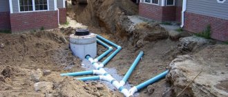
The external components of the system are painted orange (red). They have thicker walls and are designed for increased mechanical loads. This is important as the networks are laid under roads or areas where heavy loads are moving. External pipes are larger in size because they typically receive waste from multiple internal lines.
The wall thickness depends on the purpose of the pipes. For internal areas it ranges from 1.8 mm. The external elements are designed for increased load, so their walls have a thickness of 3.6 mm. As the diameter increases, this figure increases proportionally. These values are only valid for non-pressure systems.
Everything useful about sewerage -
GidKanal | Yandex Zen
