It’s hard to imagine comfort in your home without running water. And the emergence of new equipment in the form of a washing machine, dishwasher, boiler and other units has further increased its role in 21st century housing. But these units require water to come from the water supply at a certain pressure. Therefore, a person who decides to equip his home with a water supply system must know how to calculate the required water pressure in the pipeline so that all devices work properly.
For the normal functioning of the water supply system, the pressure in it must meet the standards
Definition of indicator
The pressure in the pipeline is usually divided into the following types: working, conditional, test and calculated. Without knowing their differences, it will be difficult to calculate the pressure drop of the fluid transported through the utility lines. Accordingly, when selecting suitable water supply elements, the owner will encounter difficulties that will not allow him to ensure a comfortable stay in the living space.
- Working. This is external or internal, necessarily the maximum excess pressure recorded under standard components of the water transportation process under normal conditions.
- Conditional. This indicator is used when calculating the strength of pipelines (and vessels) that operate under a certain pressure at a water temperature of 20˚C.
- Trial. This simple indicator is measured during a design test. Based on it, the behavior of system elements when pressure changes in the water supply system is monitored. This approach serves as a kind of general insurance before laying a network.
- Calculated. This means the maximum excess pressure in the cavity of the pipeline produced by the substance transported through it. It should be taken into account that not only pipes are affected, but also all elements that make up the engineering communications. It is on the basis of the calculated pressure that the wall thickness of the water pipe is determined. The functionality, as well as the duration of operation of the system and, of course, the safety of the inhabitants of the house depend on this.
The water pressure in the tap depends on the pressure in the plumbing system
10.1. Pressure calculation
Home / Publications / Literature / Bookshelf / Diver's HandbookIn diving practice, one often encounters the calculation of mechanical, hydrostatic and gas pressure over a wide range of values. Depending on the value of the measured pressure, different units are used.
In the SI and ISS systems, the unit of pressure is the pascal (Pa)
, in the MKGSS system - kgf/cm2 (technical atmosphere - at). Torus (mm Hg), atm (physical atmosphere), m water are used as off-system units of pressure. Art., and in English measures - pound/in2. The relationships between the various pressure units are given in Table 10.1.
Mechanical pressure is measured by the force acting perpendicularly per unit surface area of the body:
where p is pressure, kgf/cm2; F—force, kgf; S—area, cm2.
Example 10.1.
Determine the pressure that a diver exerts on the deck of the ship and on the ground underwater when he takes a step (i.e., stands on one leg).
The weight of a diver in equipment in air is 180 kgf, and under water 9 kgf. The area of the sole of the diving overshoe is 360 cm2. Solution. 1) Pressure transmitted by diving boots to the deck of the ship, according to (10.1): р = 180/360 = 0.5 kgf/cm
or in SI units
p = 0.5 * 0.98.105 = 49000 Pa = 49 kPa.
Table 10.1. Relationships between different units of pressure
2) Pressure transmitted by diving boots to the ground under water: or in SI units p = 0.025 * 0.98 * 105 = 2460 Pa = 2.46 kPa.
Hydrostatic pressure
liquid is everywhere perpendicular to the surface on which it acts, and increases with depth, but remains constant in any horizontal plane.
If the surface of the liquid does not experience external pressure (for example, air pressure) or is not taken into account, then the pressure inside the liquid is called excess pressure
where p is the fluid pressure, kgf/cm2; p—liquid density, gs” s4/cm2; g—gravitational acceleration, cm/s2; Y—specific gravity of liquid, kg/cm3, kgf/l; H - depth, m.
If the surface of the liquid experiences external pressure pp. then the pressure inside the liquid
If atmospheric air pressure acts on the surface of a liquid, then the pressure inside the liquid is called
absolute pressure
(i.e., pressure measured from zero - complete vacuum): where B is atmospheric (barometric) pressure, mm Hg.
Art. In practical calculations for fresh water, take Y = l kgf/l and atmospheric pressure p0 = 1 kgf/cm2 = 10 m of water. Art., then the excess water pressure in kgf/cm2 and the absolute water pressure Example 10.2.
Find the absolute pressure of sea water acting on a diver at a depth of 150 m if the barometric pressure is 765 mm Hg. Art., and the specific gravity of sea water is 1.024 kgf/l.
Solution.
Absolute pressure according to (10/4)
approximate value of absolute pressure according to (10.6) In this example, using the approximate formula (10.6) for calculation is quite justified, since the calculation error does not exceed 3%.
Example 10.3.
In a hollow structure containing air under atmospheric pressure pa = 1 kgf/cm2, located under water, a hole formed through which water began to flow (Fig. 10.1). How much pressure will the diver experience if he tries to close this hole with his hand? The cross-sectional area of the hole is 10X10 cm2, the height of the water column H above the hole is 50 m.
Rice.
9.20. Observation camera "Galeazzi": 1 - eye; 2 — cable release and cable cutting device; 3 — connection for telephone input; 4 — hatch cover; 5 — upper porthole; 6 — rubber seal ring; 7 — lower porthole; 8 — camera body; 9 — oxygen cylinder with pressure gauge; 10 — emergency ballast release device; 11 — emergency ballast; 12 — lamp cable; 13 - lamp; 14 — electric fan; 15—telephone-microphone; 16 — battery; 17 — regenerative working box; 18 — hatch cover porthole Solution.
Excess water pressure at the hole according to (10.5) P = 0.1-50 = 5 kgf/cm2.
Pressure force on the diver's hand from (10.1)
F = Sp = 10*10*5 = 500 kgf = 0.5 tf.
The pressure of the gas enclosed in a vessel is distributed evenly, if you do not take into account its weight, which, given the size of the vessels used in diving practice, has an insignificant effect. The pressure of a constant mass of gas depends on the volume it occupies and the temperature.
The relationship between gas pressure and its volume at a constant temperature is established by the expression
P1 V1 = p2V2 (10.7)
where р1 and р2 are the initial and final absolute pressure, kgf/cm2;
V1 and V2 - initial and final volume of gas, l. The relationship between gas pressure and its temperature at a constant volume is established by the expression
where t1 and t2 are the initial and final gas temperatures, °C.
At constant pressure, a similar relationship exists between the volume and temperature of the gas
The relationship between pressure, volume and temperature of a gas is established by the combined law of the gas state
. Example 10.4.
The capacity of the cylinder is 40 l, the air pressure in it according to the manometer is 150 kgf/cm2. Determine the volume of free air in the cylinder, i.e. the volume reduced to 1 kgf/cm2.
Solution.
Initial absolute pressure p = 150+1 = 151 kgf/cm2, final p2 = 1 kgf/cm2, initial volume V1 = 40 l.
Volume of free air from (10.7) Example 10.5.
The pressure gauge on the oxygen cylinder in a room with a temperature of 17°C showed a pressure of 200 kgf/cm2. This cylinder was transferred to the deck, where the next day at a temperature of -11 ° C its readings dropped to 180 kgf/cm2. There was a suspicion of an oxygen leak. Check whether the suspicion is correct.
Solution.
Initial absolute pressure p2 =200 + 1 = =201 kgf/cm2, final p2 = 180 + 1 = 181 kgf/cm2, initial temperature t1 = 17°C, final temperature t2 =—11°C. Calculated final pressure from (10.8)
Suspicions are unfounded, since the actual and calculated pressures are equal.
Example 10.6.
A diver underwater consumes 100 l/min of air compressed to a pressure of a diving depth of 40 m. Determine the free air consumption (i.e. at a pressure of 1 kgf/cm2).
Solution.
The initial absolute pressure at the immersion depth according to (10.6)
P1 = 0.1*40 =5 kgf/cm2.
Final absolute pressure P2 = 1 kgf/cm2
Initial air flow Vi = l00 l/min.
Free air flow according to (10.7)
The partial pressure of the gas
included in the air (artificial breathing mixture) is determined according to the nomogram in Fig. 10.2 or from the expression where pcm is the partial pressure of gas in the mixture, kgf/cm2; Pcm—absolute pressure of the gas mixture, kgf/cm2; C is the volumetric gas content in the mixture, %.
Example 10.7.
Determine the partial pressure of the gases included in the air supplied to the diver’s suit on the surface and at a depth of 40 m, if the analysis showed a nitrogen content of 79%, oxygen 20% and carbon dioxide 1%.
Solution.
The absolute air pressure on the surface is Рcm -1 kgf/cm2.
Rice. 10.2. Nomogram for determining the partial pressure of gas pg depending on the percentage of gas C and the absolute pressure of the gas mixture PCM
Partial pressure of gases on the surface according to (10.11): Approximately the same results can be obtained using the nomogram in Fig. 10.2.
Residual gas pressure in cylinders.
To obtain gas mixtures using the bypass method (see diagram a, Fig. 8.15), it is often necessary to know the residual pressure of the gas (oxygen) in the gas supply cylinder (cylinder K), which is equal to
where por is the residual absolute pressure of the gas (oxygen) in the supply cylinder, kgf /cm2;
Pcm is the absolute pressure of the gas mixture in the mixing cylinder, kgf/cm2; C is the gas (oxygen) content in the gas mixture by volume, %. Forward Contents Back
A simple example of calculating pressure in a pipe
As you know, not so long ago the water supply was connected to the water tower. Thanks to this structure, pressure is created in the water supply network. The unit of measurement for this characteristic is atmosphere. Moreover, the size of the container located at the top of the tower does not affect the value of this parameter; it depends only on the height of the tower.
Good to know! In practice, pressure is measured in meters of water column. When pouring water into a pipe 10 meters high, a pressure equal to one atmosphere will be recorded at the lowest point.
Let's consider an example with a house of 5 floors. Its height is 15 meters. That is, there are 3 meters per floor. A 15-meter-high tower will create a pressure of 1.5 atmospheres on the ground floor. The value of this indicator in the pipe on the second floor will already be 1.2 atmospheres. This is obtained by subtracting the height of one floor from number 15 - 3 meters, and dividing the result by 10. Having done further calculations, it will become clear to us that there will be no pressure on the 5th floor. Logic dictates that to provide water to people living on the top floor, a taller tower will need to be built. What if we are talking, for example, about a 25-story building? No one will build such large structures. For this purpose, modern water supply systems are equipped with deep-well pumps.
The outlet pressure of such a unit is calculated very simply. For example, if a deep pump, the power of which is enough to raise water to 50 meters of water column, is immersed in a well 15 meters, at the level of the earth’s surface it will create a pressure of 3.5 atmospheres (50-15/10 = 3.5).
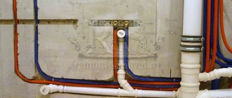
You can provide the required pressure in the system using a pump
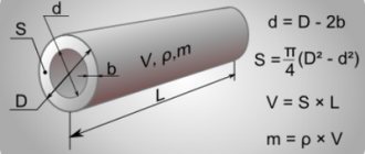
How is the thickness of a pipe calculated based on pressure?
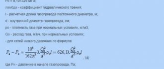
When water moves through a pipe, resistance arises from friction against the walls, as well as against various obstacles. This phenomenon is called pipeline hydraulic resistance. Its numerical value is directly proportional to the flow speed. From the previous example we already know that water pressure is different at different heights, and this feature should be taken into account when calculating the internal diameter of the pipe, that is, its thickness. A simplified formula for calculating this parameter based on a given pressure loss looks like this:
Dvn = KGSopr×Dl. tr./PD×(Spec. weight×Sk/2g),
where: Dvn. – internal diameter of the pipeline; KGSopr. – coefficient of hydraulic resistance; Lt.tr—pipeline length; PD – specified or permissible pressure loss between the final and initial sections of the pipeline; Specific weight – specific gravity of water – 1000 kg/ (9815 m/; Sk. – flow velocity m/sec.; g – 9.81 m/sec2. The well-known constant is the acceleration of gravity.
The pressure loss in the fittings and fittings of the pipeline is determined with sufficient accuracy from the losses in a straight pipe of equivalent length and with the same nominal bore.
How to calculate pipe walls by pressure
The exact calculation of this indicator for steel pipes that operate under the influence of excess internal pressure includes two stages. First, the so-called design wall thickness is calculated. The corrosion wear thickness is then added to the resulting number.
Calculation of pressure is necessary to select the thickness of the pipe walls
Advice! When making and installing a pipeline, do not install separate random inserts. In order not to provoke an accident, work only with those whose dimensions coincide with the calculated ones.
Thus, the generalized formula for calculating wall thickness is as follows:
T= RTS+PC,
where: T – desired parameter – wall thickness; RTS – design wall thickness; PC - increase for corrosive wear.
The calculated wall thickness depending on the pressure is calculated using the following formula:
RTS = VID×Dnar/230×DR×KPSh+R,
where: TYPE – internal excess pressure; Dnar. – outer diameter of the pipe; DR - permissible tensile strength; KPSh – seam strength coefficient. Its value depends on the pipe manufacturing technology. At the final stage of calculating the pipe wall based on pressure, we add the value of the PC parameter to the RTS. It is taken from the reference book.
How is flow pressure measured?
In pitot tube (double wall) designs, the shock pressure is directed forward into the flow. In conventional designs, the axis of movement of the working medium is aligned with the axis of the outer tube. Both pressure signals are piped to an indicator or transmitter.
For industrial applications, static pressure can be measured in three ways:
- Through bends in the pipe wall.
- Static pitot probes inserted into the process stream.
- Using small holes located either on the pitot tube itself or on a separate aerodynamic element.
The operating accuracy of flow meters of this design depends on the shape of the aerodynamic bodies surrounded by a constant flow of the working medium, as well as on the characteristics of its viscosity, speed and compressibility. The key to increasing accuracy is to minimize the kinetic component of pressure measurement.
Specially developed pitot sensors are also suitable for work in pulsating flows. For this purpose, a pitot probe filled with silicone oil is used, which serves to transmit the process pressure. In high-frequency pulsating applications, oil also serves as a pulsation damping and pressure averaging agent.
Pipe pressure and diameter
Correct determination of the cross-section of pipes is no less important than their selection based on the material of manufacture. If the diameter and pressure are incorrectly calculated, turbulence will occur in the pipe in the air present in it and in the water flow. Because of this, the movement of liquid through the pipe will be accompanied by increased noise, and a large amount of lime deposits will form on the inner surface of the water supply branch. In addition, it should be remembered that the existence of a dependence of pressure on the diameter of the pipe can negatively affect the throughput of the water supply system. In practice, many residents of apartments and houses were faced with a situation where, when several taps were turned on at the same time, the water pressure dropped sharply. This trouble occurs for two reasons: when the pressure has dropped throughout the entire system and when the diameter of the connected pipes is too low.
The throughput of the water supply network depends on the diameter of the pipe.
Below is a table for the maximum calculated water flow through pipelines of the most common diameters at various pressures.
Table 1
| Consumption | Bandwidth. Unit of measurement – kg/hour | |||||||||
| Du pipe | 100 | 80 | 65 | 50 | 40 | 32 | 25 | 20 | 15 | |
| mbar/m | Pa/m | 0.3 m/sec | 0.15 m/s | <0.15 m/sec | ||||||
| 3,00 | 300 | 56160 | 27900 | 18000 | 8892 | 4680 | 3078 | 1415 | 767 | 331 |
| 2,80 | 280 | 54360 | 26928 | 17338 | 8568 | 4356 | 2970 | 1364 | 742 | 317 |
| 2,60 | 260 | 52200 | 25920 | 16740 | 8244 | 4356 | 2855 | 1310 | 713 | 306 |
| 2,40 | 240 | 50400 | 24876 | 16056 | 7920 | 4176 | 2740 | 1256 | 680 | 288 |
| 2,20 | 220 | 47880 | 23760 | 15336 | 7560 | 3996 | 2617 | 1202 | 652 | 281 |
| 2,00 | 200 | 45720 | 22644 | 14580 | 7200 | 3780 | 2488 | 1151 | 619 | 266 |
| 1,80 | 180 | 43200 | 21420 | 13824 | 6804 | 3589 | 2354 | 1080 | 583 | 252 |
| 1,60 | 160 | 40680 | 20160 | 12996 | 6408 | 3373 | 2210 | 1015 | 547 | 234 |
| 1,40 | 140 | 38160 | 18792 | 12132 | 5976 | 3143 | 2059 | 943 | 511 | 220 |
| 1,20 | 120 | 35100 | 17352 | 11196 | 5508 | 2898 | 1897 | 871 | 472 | 102 |
| 1,00 | 100 | 31932 | 15768 | 10152 | 5004 | 2632 | 1724 | 788 | 425 | 184 |
| 0,975 | 97,5 | 31500 | 15552 | 10044 | 4932 | 2596 | 1699 | 778 | 421 | 180 |
| 0,950 | 95,0 | 31104 | 15372 | 9900 | 4860 | 2560 | 1678 | 767 | 414 | 176 |
| 0,925 | 92,5 | 30672 | 15156 | 9756 | 4788 | 2524 | 1652 | 756 | 407 | 176 |
| 0,900 | 90,0 | 30240 | 14940 | 9612 | 4716 | 2488 | 1627 | 745 | 403 | 173 |
In most risers, the average pressure value is in the range of atmospheres.
Definition of Pascal's Law
So, we come to the formulation of Pascal’s law, and it sounds like this:
The pressure exerted on a liquid or gas is transmitted to any point equally in all directions.
Please note that the law only applies to liquids and gases. The fact is that molecules of liquid and gaseous substances under pressure behave completely differently from molecules of solids. While liquid and gas molecules move almost freely, solid molecules cannot do this. They can only fluctuate, deviating slightly from their original position. It is thanks to the free movement of gas and liquid molecules that they exert pressure in all directions.
Let's consider the experiment with Pascal's ball to make it clearer.
Let's attach a hollow ball with many small holes to the pipe with the piston. Pour water into the ball and press on the piston. The pressure in the pipe will increase and water will pour out through the holes, and the pressure of all jets will be the same. The same result will be obtained if instead of water there is gas in the ball.
Important point
The Earth has an atmosphere. This atmosphere creates a pressure that adds to all the others. That is, if we press our hand on the table, then the pressure that the table experiences is the pressure of our hand plus atmospheric pressure.
Calculation of home plumbing
From a practical point of view, pressure in a water supply system is most often associated with the volume of water supplied per unit of time, that is, with the throughput of the water supply branch. In this context, the issue of calculating household water supply will be considered. After studying the passport data of devices and units that consume water, the total consumption is summed up. Then the consumption of all installed and used water taps is added to the resulting figure.
For home water supply running from a well, the choice of pipes depends on the power of the pump
Helpful information! One such plumbing device passes about 5-6 liters of water through itself in one minute.
After this, all the numbers are summed up, and the output is the total water consumption in the house. Taking this data into account, a pipe with a diameter is purchased that will provide the required pressure and, accordingly, the amount of water to all water taps operating simultaneously.
If the home water supply is planned to be connected to the city network, the owner has no choice; he will be forced to use what is available. It’s a different matter if we are talking about a private house powered by a well. Then you should buy a pump that can provide the water supply with pressure that matches the costs. The choice is made according to the passport data of such a unit. The table below will help you determine the diameter.
table 2
| Pipe capacity | Pipe diameter and length | ||
| Throughput, l/min | Pipe diameter | Pipe diameter | Pipeline length, meters |
| 75 | 38 | 32 | More than 30 |
| 50 | 32 | 25 | |
| 30 | 25 | 20 | Less than 10 |
Here are the parameters of only the most commonly used pipe products.
Pressure
A person walking on loose snow will constantly fall into it.
But on skis he will be able to move on the same snow calmly. It would seem that nothing changes - a person acts on the snow with the same force both on skis and without them. The fact is that “falling” into the snow is characterized not only by force - it also depends on the area on which this force acts. The surface area of the ski is 20 times larger than the surface area of the sole, so a person standing on skis acts on every square centimeter with a force 20 times less than without them.
Or, for example, if you stick buttons into a cork board with the same force, the button with the more pointed end will go in easier, since its area is smaller.
To summarize: the result of a force depends not only on its magnitude, direction and point of application, but also on the surface area to which this force is applied.
Now let’s confirm this conclusion with experiments, like real physicists.
Let's take a small board and drive nails into its corners. We will also take a container with sand and place the structure of boards and nails in this container. First, let's place the structure with its caps down and place a weight on it. The structure will not sink into the sand, but will only go slightly deeper into it.
Then we turn the structure over so that the heads of the nails are on top and also place a weight on the board. Now the structure will sink into the sand.
The result of the force depends on how much force acts on each unit of surface area.
In all examples we talked about the action of a force perpendicular to the surface. To characterize this action, the quantity pressure .
| Pressure p = F/S p —pressure [Pa] F - force [N] S – area [m2] |
Modern means
If you don’t have time or are not inclined to mathematics, you can calculate the water flow through the pipeline taking into account the pressure drop using an online calculator. The Internet is replete with sites with tools. To make a hydraulic calculation, it is necessary to take into account the loss coefficient. This approach involves choosing:
- pressure drop per linear meter of pipeline;
- length of the section;
- internal diameter of the pipe;
- type and material of the plumbing system (plastic, reinforced concrete, asbestos cement, cast iron, steel). Modern online calculators even take into account, for example, the lower roughness of a plastic surface compared to a steel one;
- method for calculating resistance.
In addition, the user has access to options for taking into account additional characteristics of pipelines, in particular, such as the type of coating. For example:
- cement-sand, applied by various methods;
- external polymer cement or plastic;
- new or serviced pipelines for a certain period of time with a bitumen coating or without a protective internal coating.
If the calculation is done correctly, provided that the installation is carried out in compliance with all requirements for the water supply system, there will be no complaints.