MAIN DIMENSIONS
2.1. The designation of thread size, pitches and nominal values of the main dimensions of conical (external and internal) threads must correspond to those indicated in the drawing. 2 and in table. 2.
l
1
—
working thread length;
l
2 - the length of the external thread from the end to the main plane.
Crap. 2
table 2
Dimensions in mm
| Thread size designation | Step P | Thread diameters in the main plane | Thread length | |||
| d = D | d 2 = | d 1 = | l 1 | l 2 | ||
| 1/16 | 0,907 | 7,723 | 7,142 | 6,561 | 6,5 | 4,0 |
| 1/8 | 9,728 | 9,147 | 8,566 | |||
| 1/4 | 1,337 | 13,157 | 12,301 | 11,445 | 9,7 | 6,0 |
| 3/8 | 16,662 | 15,806 | 14,950 | 10,1 | 6,4 | |
| 1/2 | 1,814 | 20,955 | 19,793 | 18,631 | 13,2 | 8,2 |
| 3/4 | 26,441 | 25,279 | 24,117 | 14,5 | 9,5 | |
| 1 | 2,309 | 33,249 | 31,770 | 30,291 | 16,8 | 10,4 |
| 11/4 | 41,910 | 40,431 | 38,952 | 19,1 | 12,7 | |
| 11/2 | 47,803 | 46,324 | 44,845 | |||
| 2 | 59,614 | 58,135 | 56,656 | 23,4 | 15,9 | |
| 21/2 | 75,184 | 73,705 | 72,226 | 26,7 | 17,5 | |
| 3 | 87,884 | 86,405 | 84,926 | 29,8 | 20,6 | |
| 31/2 | 100,330 | 98,851 | 97,372 | 31,4 | 22,2 | |
| 4 | 113,030 | 111,551 | 110,072 | 35,8 | 25,4 | |
| 5 | 138,430 | 136,951 | 135,472 | 40,1 | 28,6 | |
| 6 | 163,830 | 162,351 | 160,872 | |||
Shorter thread lengths may be used.
2.2. Numerical values of diameters d
2 and
d
1 are calculated using the following formulas
d
2 =
D
2 =
d
- 0.640327
P
, (1)
d
1 =
D
1 =
d
- 1.280654
P
. (2)
Numerical values of diameter d
established empirically.
2.3. Difference between actual dimensions l
1 -
l
2 must be no less than the difference between the nominal sizes
l
1 and
l
2 indicated in table. 2.
2.4. The length of the internal tapered thread must be at least 0.8 ( l
1 - D1
l
2), where D1
l
2 - in accordance with table. 3.
2.5. The designation of thread sizes, pitches and nominal values of the outer, middle and inner diameters of the internal cylindrical thread must correspond to those indicated in the drawing. 3 and in table. 2.
2.6. The design of parts with internal threads (conical and cylindrical) must ensure screwing in of external conical threads to a depth of at least ( l
1 + D1
l
2).
Crap. 3
Classification of threads, thread designation in the drawing
In mechanical engineering, standard cylindrical and conical threads of various types are used, differing from each other in purpose and parameters. The main element of the thread is its profile (Figure 14.1).
The thread designation includes the letter designation of the thread type and thread parameters. When designating a thread, its outer diameter (larger in size) is indicated.
For all threads, except conical and cylindrical pipe threads, designations are applied to the outer (larger) diameter and placed above the dimension line, on its extension or on the flange (Figure 2).
- Order drawings
Helix line. Basic thread parameters. Thread image
Products with screw surfaces are widely used in technology. These are fasteners used to connect parts of machines and mechanisms (bolts, nuts, screws, studs, threaded parts for connecting two parts), parts with helical surfaces used to convert rotational motion into translational motion (a worm paired with a worm wheel).
- The helix is obtained using a cutter.
- The thread is made using a cutter or tap and a die.
- A thread is characterized by pitch and stroke.
- There are right and left screw surfaces.
- Raising the helix to the right gives a right-hand thread (Figure a). b) - left-hand thread
Depending on the number of helical lines, threads are divided into single and multi-start.
Figure c) shows a double-start thread (n = 2)
Thread pitch is the distance between two adjacent screw flanges.
Thread lead is the distance between two adjacent helical protrusions of the same helical line.
, where is the number of visits
Drawing the projection of a helical surface is a very labor-intensive process. Therefore, in the drawings, the thread is depicted conventionally - as a solid thin line (thread cavity), and in views where the rod or hole is projected as a circle, the thread is depicted as an arc of a circle, approximately equal to the circle, open anywhere, but not on the center lines.
The distance between the solid main and thin lines is not less than 0.8 mm and not more than the thread pitch.
The thread boundary is drawn to the line of the outer diameter of the thread with a solid main thick line.
Invisible threads are shown with dashed lines of the same thickness along the outer and inner diameters
The designation of conical threads and cylindrical pipe threads refers to the contour of the thread (main solid line) and is applied only on the shelf of the leader line (Figure 15.3).
A rectangular thread with a non-standard profile is depicted as shown in Figure 15.4, with all dimensions applied. Additional information - the number of entries, the direction of the thread, etc. - is marked on the shelf with leader lines with the addition of the word “Thread”.
Elements and parameters of a rectangular thread can also be shown on the extension element (Figure 15.5).
The rule should be firmly remembered: in threaded connections shown in section, the thread of the rod covers the thread of the hole (Figure 15.6 a, b). Pay attention to the fact that in sections the shading is brought to solid main lines.
Thread run -out is the length of the section of an incomplete profile in the transition zone from the thread to the smooth part of the part. Usually it is not depicted (Figure 15.7)
Chamfer - A beveled part of the surface of a part at the end or in transition areas, facilitating its assembly with other parts (the beveled edge of a rod or hole).
On a rod, the smaller diameter of the chamfer is smaller than the internal diameter of the thread. In a hole, the larger diameter of the chamfer is larger than the outer diameter of the thread.
The thread line must intersect the chamfer line.
Chamfers on a rod and in a threaded hole on a plane perpendicular to the axis of the rod or hole are not shown (Figure 15.8 a and b).
If the chamfer is not at an angle of 45°, then the chamfer designation is indicated by the angle as shown in Figure 15.9
External and internal grooves are made to exit the thread-cutting tool so that the thread has a full profile - without runs.
The dimensions of the grooves are applied on remote elements in accordance with GOST 10549-80 depending on the thread pitch
TOLERANCES
3.1. Axial displacement of the main plane D1 l
2 external and D2
l
2 internal threads (Fig. 4) relative to the nominal location should not exceed the values specified in table. 3.
The displacement of the main plane is total, including deviations of the average diameter, pitch, angle of inclination of the side of the profile and cone angle.
3.2. The maximum deviations of the average diameter of the internal cylindrical thread must correspond to those indicated in the table. 3.
Crap. 4
Note. In the main plane, the average diameter has a nominal value.
Table 3
Dimensions in mm
| Thread size designation | Offset of the main thread plane | Maximum diameter deviations D 2 internal cylindrical threads | |
| ±D1l 2 | ±D2l 2 | ||
| 1/16 | 0,9 | 1,1 | ±0,071 |
| 1/8 | |||
| 1/4 | 1,3 | 1,7 | ±0,104 |
| 3/8 | |||
| 1/2 | 1,8 | 2,3 | ±0,142 |
| 3/4 | |||
| 1 | 2,3 | 2,9 | ±0,180 |
| 11/4 | |||
| 11/2 | |||
| 2 | |||
| 21/2 | 3,5 | 3,5 | ±0,217 |
| 3 | |||
| 31/2 | |||
| 4 | |||
| 5 | |||
| 6 | |||
Note. Limit deviations ±D1 l
2 and ±D2
l
2 do not apply to threads with lengths shorter than those indicated in table. 2.
3.3. It is allowed to connect an external conical thread with an internal cylindrical thread of accuracy class A according to GOST 6357-81.
3.4. Recommended maximum deviations of individual thread parameters are given in the reference appendix.
Image of thread on drawings
According to GOST 2.311-68, threads of all types are depicted conventionally.
On the rod
The thread on the rod is depicted by solid main lines (s) along the outer diameter and solid thin lines
In the hole
When making a cut, the thread in the hole is depicted with solid main lines along the internal diameter of the thread and solid thin lines along the outer diameter (Fig. 5). In the images obtained by projection onto a plane perpendicular to the axis of the hole, an arc is drawn along the outer diameter of the thread, approximately equal to 3/4 of the circle, open at any place.
The thread boundary in the hole is shown with a solid main line, drawing it to the lines of the outer diameter of the thread.
Hatching lines in sections and sections are drawn to the lines of the outer diameter of the thread on the rod and to the lines of the internal diameter in the hole, i.e. in both cases to the solid main lines.
In connection
On sections of a threaded connection, when depicted on a plane parallel to its axis, only that part of the thread that is not covered by the thread of the rod is shown in the hole (Fig. 6).
NOTATION
4.1. The thread symbol must include: letters ( R
- for tapered external thread,
Rc
- for tapered internal thread,
Rp
- for cylindrical internal thread) and thread size designation.
The symbol for left-hand threads is supplemented with the letters L H.
Examples of thread designations:
external pipe tapered thread 11/2: R
11/2
internal pipe tapered thread 11/2: Rc
11/2
internal pipe cylindrical thread 11/2: RP
11/2
left hand thread:
R
11/2
L.H.
;
Rc
11/2
L.H.
;
R.P.
11/2
LH.
4.2. A threaded connection is designated by a fraction, for example, or Rc
/
R
, the numerator of which indicates the letter designation of the internal thread, and the denominator - the external thread, and the thread size.
Examples of threaded connection designations:
pipe conical thread (internal and external);
; ;
internal pipe cylindrical thread (with tolerances according to this standard) and external pipe tapered thread:
; ;
internal pipe cylindrical thread of accuracy class A according to GOST 6357-81 and external pipe conical thread:
; .
Inch tapered threads
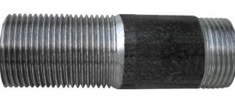
If some kind of stronger twist is required, then a conical inch notch is optimal for this purpose. Such a spiral is most often used in pipelines with high pressure of the transported medium - gas or liquids. Also, conical cutting has proven itself well when twisting metal pipes in underground highway routes laid with great depth.
When using conical notches, the joints must be sealed with mastics, bitumen or adhesives. The designation for external screw conical thread is the symbol “R”, the internal notch is indicated by the group of symbols “Rc”. Cone-shaped threads are made on structural elements whose final diameter is smaller than the initial one, that is, it has the shape of a cone in cross-section. It is precisely because of the cone-shaped body of the product that when the elements are twisted, the thread is deformed, compressed and flattened, which contributes to the greatest reliability of the connection of steel or cast iron structures.
Using a conical inch notch, elements of water supply, gas pipelines and heating systems are connected. The metric cone relief is widely used, the distinctive feature of which is the creation of connections with an external conical notch and an internal cylindrical helical notch.
