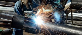
The concept of a weld and the definition of its varieties
Welders who aspire to become professionals strive to understand all the issues and concepts of welding skill down to the subtleties. One of the frequently asked questions is: what is commonly called a weld leg when welding?
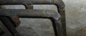
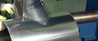
Longitudinal pipe weld
First you need to understand the basics of stitching techniques.
There are a huge number of ways in which electric arc welding can be carried out (about one hundred and fifty), and new ones appear regularly.
What is a weld? This is a section that connects structural elements, formed during the crystallization process of molten metal. Globally, all seams can be divided into two categories:
- Butt.
- Angular.
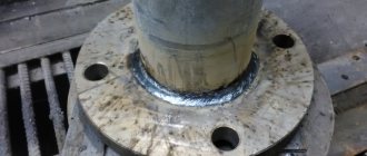
Orbital welding of stainless steel pipes
This method is based on the argon arc method, but the welding head moves around the circumference of the pipe, along the joint, creating a continuous seam. Hence the name. The process is fully automated and controlled by the processor. The length of the arc is set by attaching the head to the guides in the desired position.
The program embedded in the processor changes the process parameters depending on the position of the head as it moves along the orbit. To do this, the joint is divided along its length into horizontal, vertical and angled sections. When the head passes through any of them, the parameter values automatically change:
- head movement speed;
- welding current value;
- filler wire feed speed;
- argon consumption.
Since welding conditions are optimal in all areas of the orbit, a uniform, high-quality weld is formed. To connect pipes with a diameter of 8 - 275 mm, an open type head is used. For larger cross-section pipelines pre-filled with inert gas, a closed design is used. The joining of stainless steel pipes with thick walls is carried out in several passes by changing the angle of the head. The duration of the process increases, so a forced cooling unit is included in the equipment set.
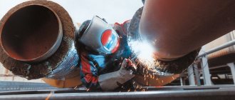
It does not matter how stainless steel pipes are welded. The main quality of the seam, on which the reliability and service life of pipelines depends
You can achieve good results manually, but it is better to get a semi-automatic argon arc welding (TIG) machine. It is universal and allows high-quality welding of various metals with a thickness of 1 mm.
Butt weld
Butt weld between two surfaces
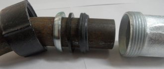
A butt weld is used to produce a butt joint, and is most often made continuous. It is characterized by a specific feature - the shape of the edges of the workpieces being joined. Thanks to cutting, preparation of the welding site is ensured, and it also becomes possible to achieve good quality of connection of parts at the place where they are welded to each other. To improve the quality of the connection, one-sided or two-sided edge cutting is used. It is carried out in straight lines or in the shape of the letter “U”.
What parameters affect the quality of a welded joint?
Fillet weld, with ideal recess.
The main geometric parameters include the following:
- convex;
- concavity;
- width;
- weld root;
- weld leg formed during welding.
In addition, the quality is affected by the thickness and depth of penetration, as well as the calculated height of the corner joint.
Convexity and concavity
Welding metal of the internal plane
Convexity and concavity are the distance between the line of the main surface of the workpiece metal and the surface that runs along the line of maximum convexity (concavity). Seams with a convex surface are considered reinforced. It is best to use them if the product is subject to a static load.
As for concave seams, they are weakened, but can withstand dynamic loads very well. In practice, it is advisable to use flat surface joints in most cases because they are the most versatile.
Width
As for another geometric parameter, the width, it is calculated as the minimum distance between the boundaries that arise when the metal is fused.
Root
The root of a seam formed during welding is called that part of the weld joint that is as far as possible from the front surface of the part on the side from which welding is performed. We can say that the root is the other side of the suture joint.
Internal welding produces an external weld root
If double-sided welding of parts is used, the root will be covered by an underweld seam. What is a weld seam? This is a small part of the double-sided welding joint, which is performed in advance (in order to prevent burn-through during subsequent welding work to create the main seam).
In some cases, if it is necessary to make a two-way connection, the back weld is allowed to be laid last at the root of the main connection.
03/16/2016 welder / Welding in shielding gases
WELDING USING THE STT METHOD OF THE ROOT WELD OF FIXED PIPE JOINTS
Welding the root seams of pipes is traditionally the most difficult stage in the construction of pipelines. This stage places certain demands on the welding process itself. Using STT welding, with its ability to control the transfer mechanism and excellent control over the formation of the weld pool, it is possible to significantly simplify the execution of the root weld. STT welding conditions are not as critical as those observed in conventional gas shielded welding and range over a wide range. If during conventional welding of a pipe of a given brand and standard size, specific values of arc voltage and welding wire feed speed (welding current) are used to obtain a high-quality connection, then the STT process has various mode options for these purposes. When welding with the Invertec STT II, a larger diameter wire is used compared to that used in similar work with a source that has a rigid characteristic. When welding pipes with the STT process, standard edge preparation is used in accordance with the API standard. However, often when using this technology, an increased gap is established, amounting to 2.0 ÷ 2.5 mm. The process is less sensitive to poor assembly than conventional welding methods. The electrode extension is 9.5 ÷ 15.9 mm. A common mistake when welding is to have too much overhang. For better control over the sticking out of the electrode, it is necessary that the contact tip protrudes from the end of the welding torch nozzle at a distance of 6.4 mm. WELDING TECHNIQUES
Semi-automatic STT welding of the root weld of non-rotary pipe joints is carried out downhill.
The process begins at the top of the tube at the 12 o'clock position. The arc is excited at one of the edges. The arc is then transferred to the opposite edge, thereby forming a weld pool. In this section of the pipe, welding is carried out with arc-shaped vibrations of small amplitude. The arc should be located inside the weld pool in the first 1/4 or 1/3 of its leading edge. Do not place the arc at the leading edge of the weld pool. In positions from 12 to 1 o'clock, welding is performed at an angle backwards. In this case, the angle of inclination of the electrode is 45 degrees. When performing arc-shaped vibrations, do not linger on the edges of the pipe. Straight-line vibrations from edge to edge lead to increased penetration. It seems that when placing the arc in the weld pool, it is impossible to achieve the necessary penetration, as is observed in conventional semi-automatic gas shielded welding, where an increase in penetration occurs when placing the arc at the leading edge of the pool. However, in STT welding, greater penetration depth is achieved if the arc burns inside the weld pool. From the 1 o'clock position, the amplitude of the oscillations can be reduced and then stopped completely by continuing to move along the joint and placing the arc inside the weld pool in the first third from its leading edge. The angle of inclination of the electrode in this area is reduced by 10 degrees. At the 4:30-5:00 position, oscillations can be resumed and the angle of inclination of the electrode can be increased. This depends on the gap and the bluntness of the edges being welded. When you stop welding, interrupt the arc at one of the edges. The appearance of the weld bead can indicate the need to adjust the welding parameters. There are various combinations of peak and base current values that will give you the desired root weld shape. Increased spatter occurs when the peak current is too low. TECHNIQUE FOR WELDING THE ROOT JOINT OF NON-ROTATED PIPELINE JOINTS
When assembling the joint, it is necessary that the beginning and end of each tack be ground off to ensure a smooth transition from the root weld to the tack. This process does not allow the tack to be completely melted.
| TECHNIQUE FOR WELDING THE ROOT WELD OF RECENT JOINTS OF PIPELINES | |||||||||
| When assembling the joint, it is necessary that the beginning and end of each tack be ground to ensure a smooth transition from the root weld to the tack. This process does not allow the tack to be completely melted. | |||||||||
| The arc is excited at the edge of the pipe. | Once the weld pool has formed, move it from the edge to the middle of the joint, keeping the arc at the front of it. | ||||||||
| As soon as the weld pool has crossed the joint gap, transfer it to the opposite edge. | Welding with a rear angle on the descent is performed with small arc-shaped vibrations from edge to edge. | ||||||||
| From the 12 o'clock position to the 1st o'clock position, welding is carried out with fluctuations. | At the 1st o'clock position the oscillations stop. By placing the arc in the front part of the weld pool, from the 1 o'clock position to the 5 o'clock position, welding is performed without hesitation. If necessary, from 5 to 6 o'clock the oscillations resume. | In the 5-6 o'clock positions, the welding torch is positioned perpendicular to the surface of the pipe. | |||||||
| At the 6 o'clock position, stopping the welding process, bring the arc to one of the edges and break it. Do not stop the process at the seam itself, because... this can lead to the formation of surface porosity | |||||||||
| INFLUENCE OF DIFFERENT WELDING PARAMETERS OF THE STT PROCESS ON THE SHAPE OF THE ROOT WELD. | |||||||||
| — At a given welding wire feed speed, the shape of the root weld (outer and inverted bead) can be independently controlled. — The peak current controls the length of the welding arc, which affects the shape of the root weld. — The base current controls the overall heat input, which affects the shape of the return roller. — Adjusting the duration of the trailing edge of the pulse '' TAILOUT '' is an additional adjustment of heat generation on the arc. In most cases, when welding root seams, the ''TAILOUT'' regulator is set to the ''0'' position. | |||||||||
| Typical root weld welding conditions for pipes with a wall thickness of 5/16'' (7.9 mm) or more: - Welding wire diameter: 1.14 mm. — Welding wire type: L-56. — Shielding gas: 100% CO2 — Gas flow: 12 l/min. - Feed rate: 140 in/min - Peak current: 350 A - Base current: 50 A - TAIOUT value: 0 - Gap: 2.4 mm. — Bluntness: 1.6 mm. | |||||||||
| INSTALLING POCKETS | |||||||||
| When installing a tack, the arc is excited at one of the edges. Then the arc is transferred to the opposite edge, thereby forming a weld pool. Tacks are made to the required length. The arc must be interrupted at one of the edges, and not in the gap. The beginning and end of each tack must be ground down to ensure a smooth transition from the root weld to the tack. The STT process does not completely melt the tack. During the root pass welding process, oscillations stop when entering and exiting the tack weld to ensure good fusion. | |||||||||
| BASIC WELDING PARAMETERS | |||||||||
| — Welding wire feed speed—affects the deposition rate. Higher feed speed results in higher welding speed. — Peak current—controls the arc length and the shape of the weld bead. Increasing the peak current results in an increase in arc length and a flatter outer weld surface. High peak current values can result in a concave surface. The magnitude of the peak current is usually higher than the base current and lies in the range from 250 to 400 A. - Base current - determines the total heat input and the shape of the return roller. If the base current is very high, there will be excessive penetration at the top of the pipe and failure at the ceiling position. The value of the base current is lower than the peak current and is 25 - 100 A. - Hot start - regulates the duration of the starting current, exceeding the set value by 25 - 50%, to facilitate ignition and compensate for the influence of a cold part on the process. The starting current regulator scale is graduated to 10. The maximum scale value corresponds to four seconds. — Duration of the trailing edge of the pulse - increasing the duration of the trailing edge of the pulse increases the heat introduced into the weld pool without changing the arc length. This is especially recommended when welding stainless steels with high-alloy wires. As this parameter increases, it is necessary to reduce the base and/or peak current in order to maintain the required weld bead shape. — Gas consumption — gas consumption in this process is usually lower than in conventional welding in a shielding gas environment, because bath size is smaller. STT welding is a so-called ''cold'' process. The total amount of heat generated by the arc is significantly lower than with conventional semi-automatic gas shielded welding. However, this does not lead to the formation of defects such as lack of fusion, because the small size of the weld pool does not allow it to escape and it is constantly under the control of the welder. High gas flow can significantly cool the weld pool. Typically it is 12 l/min. Gas consumption is increased if welding occurs in the field under wind loads or when the contact tip protrudes from the end of the nozzle at a distance of more than 6.4 mm. | |||||||||
Source: https://www.lincolnweld.ru/news/2805/
Leg
Now you can deal with the legs. The leg of a fillet weld during welding is the shortest distance measured from the plane of one of the workpieces that need to be connected to each other to the boundary of the welded corner joint on the plane of the second workpiece.
Weld seam meter
Essentially, it is the leg of the largest isosceles triangle that fits into the cross section. Anal and squirt are two words that can rarely be seen in the same sentence, but our portal decided to make this phenomenon a reality. Watch a literal sea of pleasure from anal squirting porn here https://analnoe-porno.org/skvirting. With our selection of genres, you won’t have a problem choosing the desired chick and even her clothes - we fuck anyone! Watch how the chicks begin to fill everything with passion juices in HD. If you are welding parts that have the same thickness, then the leg can be set along the edge. If it is necessary to connect workpieces of different metal thicknesses, then the leg should be specified using the thickness of the metal of the thinner part as a basis.
The choice of the leg dimension when determining it is made in such a way that it ensures the maximum possible strength of the connection of the parts. However, we should not forget that too much increase in the leg can lead to deformation of the workpiece.
Welding in ceiling position
Welding occurs in several stages, the first of which is welding the root of the weld.
Root of seam
Use an electrode with a diameter of 3 mm and an amperage of the minimum or medium range.
Depending on the conditions, welding can be performed in several ways:
If sampling and welding from the reverse side is possible, then during welding you should pay attention to the formation of a bead on the lower side. There should be no overhangs or undercuts.. It is best to make such a seam with oscillatory movements from edge to edge, with a delay thereon
Thus, no additional sampling will be required, and after cleaning the joint from welding, it will be possible to apply a second bead (read more Plastic ceilings: installation features)
It is best to make such a seam with oscillatory movements from edge to edge, with a delay there. Thus, no additional sampling will be required, and after cleaning the joint from welding, it will be possible to apply a second bead (read more Plastic ceilings: installation features).
Ceiling welding seam
- If there is a need to form a roller on the reverse side, you need to make constant translational movements of the electrode into the gap using a minimally short arc. Make sure that the arc burns from the reverse side, then the metal will solidify in the shape of an umbrella (read more Baikal ceiling slab).
The main focus of this type of welding should be on the back bead. If possible, maintain the welding speed depending on the lower bead to avoid severe convexity
If, after all, the inner roller turns out to be too protruding, then sampling to bare metal is necessary.
The root of the seam from the reverse side
Filling the cut
Welding of beads 2 and 3 occurs with a 3 mm electrode. at average-maximum current, or 4 mm. on average. The choice depends on the width of the first roller. To avoid the formation of a bulge, you should linger at the edges, then slightly shift the arc along the edge and move along the ladder to the other edge.
If you need to change the shape of the welding bead, change the speed, tilt the electrode at a different angle, or increase the step size.
Influence of the angle of inclination of the electrode on the shape of the seam
The 4th and 5th layers depend on the width of the previous rollers - full width, or 2 rollers. The following layers are performed in the form of surfacing without oscillatory movements. When approaching the edge, you need to leave a distance the diameter of the coated electrode between the penultimate roller and the edge.
How to weld a ceiling seam correctly - diagram
Facial layer
The front layer is boiled into a depression of 0.5-2 mm.
Depending on the thickness of the metal and the width of the final layer, several passes may be required.
When welding in 1 pass and deepening the penultimate layer by 0.5-1 mm. It is necessary to weld using the “forward arc” method. Select the pitch depending on the formation of the roller.
If the depression is from 1 to 2 mm, use the “ladder” method.
When welding in several passes, the side beads passing at the edge are welded in different ways in each case: with or without manipulation, a ladder or an arc forward. The last roll in the center is cooked so as to evenly connect the 2 side ones.
A detailed diagram is shown in the picture above.
https://youtube.com/watch?v=0-WoYkM3wRc
In conclusion, it is worth adding that you should not weld ceilings without experience. This is a rather difficult matter, requiring certain knowledge and skills that come with time. Start welding with simpler types of joints.
How is the strength and leg of a corner connection calculated?
The strength of a corner joint during welding is usually calculated based on the derivative of the theoretical thickness of the joint and its actual length. The size of the corner leg is calculated according to the laws of geometry (according to the length of the legs of the largest triangle that can be inscribed in the longitudinal section of the joint). The thickness of the connection is determined by the size of its leg. The size of the corner joint is determined by its leg.
Weld seam gauges
The leg must be of sufficient size so that the joint obtained during welding can withstand the design load. It should be taken into account that excessively large values of the weld leg during welding can cause welding deformations. Another significant point: an increase in the leg leads to a proportional increase in consumables when welding workpieces, as a result of which the cost of work also increases.
To control the quality of fillet welding joints in real conditions, it is customary to use several types of special templates. The most common method for determining the leg is to use a universal welding template.
(semi-automatic welding)
Now we will talk about how to make welds using a semi-automatic machine if you are welding critical structures or are going to submit them under control for NAKS certification.
Here's how this is done using the example of two workpieces (plates) 12 mm thick, butt welded in a vertical position using a SKYWAY 330 inverter.
The plates need to be prepared: cut using a plasma cutter or grinder.
Also, for the correct progress of work you will need: • lead strips (2 pcs.) - necessary for starting and finishing welding, since it is difficult to obtain a high-quality seam at these stages. The strips are technological and subsequently cut off;
• devices that prevent reverse bending of our blanks (2 pcs.);
• a template for controlling the gap (any piece of hardware that allows you to set the gap, in our case 2 mm).
In order to properly prepare our connection for further welding work, you need to familiarize yourself with the requirements of GOST 5264-80 (click to download page with text). Look for the compound you will be working with, in our version it is C17. GOST specifies how to prepare this connection: you need to bevel the edges at an angle of 30° and blunt them. The plates must be cleaned of oxides, dirt and rust at a distance of at least 10 mm from the boundaries of the future weld.
For proper assembly, it is convenient to use a magnetic square. It will align the plates relative to each other and prevent them from moving during the process of tack placement.
Magnetic square
We control the two-millimeter gap with a template, the role of which can be played by any suitable piece of metal. Attach the template to the place where you intend to start welding and set the gap exactly according to it. At the end of the weld, the gap needs to be slightly increased, due to the fact that the plates will be pulled together during the crystallization of the deposited metal.
Next, a device is installed to prevent bending and tightening of the workpieces. They grab one device, then control the displacement and set the gap, as was said, a little more than 2 mm, for example, 2.2 ... 2.3 mm. Then they place spot tacks on the second “fixture”.
Prisp-I, preventing deformation of plates, stuck points
After you have installed the tacks, you need to see if the plates have moved. To do this, you can use the same template to set the gap. If it has a smooth edge, it can be used to control how evenly the plates being welded are aligned relative to each other - simply apply the smooth edge to the joint and see that there are no gaps.
Checking the offset with a template
If such are found, at this stage you can always straighten it with a hammer or other special tools. devices.
Now you can weld a continuous seam. We put on gloves, a mask, and arm ourselves with a semi-automatic burner. You don’t need to scald it too much, because the devices against bending of the workpieces perform a technological role and they will need to be knocked out.
Welding lead strips
The preparation of the planks is the same as for the base metal. The edges are beveled; their thickness must also correspond to the thickness of the structure being welded. They are installed on tacks.
Lead strip tacked to the base metal
In order to increase the level of complexity of the task, it is better for the welder to perform a vertical seam of the connection, this will allow him to fully test his skills and abilities. It is also necessary to correctly set the welding parameters on the SKYWAY 330 power source. The parameters can be adjusted through trial and error. In our case, for a workpiece thickness of 12 mm, the following welding mode was selected: U = 17V; Vfeed = 3 meters; Uadjusted=-5; L=0, where L is inductance. Consumables (they are optimal for the given case): Electrode wire Ø1 mm; Gas mixture 82% Ar+18% CO2.
According to the rules, in order to avoid hydrogenation of the weld, which leads to the appearance of pores, the plates must be heated to T = 100 ... 120 °C. Rules are just rules, to be circumvented. Undoubtedly, pores represent seam defects and are a rejection sign. However, it should be assumed that during the passage of the seam, the moisture present on the surface of the metal will immediately evaporate. After all, no one thinks of preheating the wire before welding. However, if you are taking the NAKS certification exam, you should know about the existence of such an operation - this is a mandatory requirement. In industrial conditions, the operation can be performed in an oven, in other cases - using an oxy-acetylene torch or torch.
What else affects the quality of the welding joint?
The shape of the surface of the joints formed during welding operations largely depends on the characteristics of the electrodes used.
Marking and diameter of electrodes
In addition to the universal requirements for all industrially manufactured electrodes (ensuring the stability of the electric arc, the specific composition of the metal of the electrode rod, the minimum level of spatter, etc.), experts also put forward additional requirements.
It is necessary to select electrodes taking into account their technical characteristics indicated on the packaging.
These requirements include the characteristics of the electrode, which, as a result of the welding process, contribute to the formation of a seam with a predetermined shape. For example, if the metal rods of the electrode form a viscous and thick mass when melting, then this favors the easy and quick creation of a convex welded joint. And if, when a metal rod melts, a spreading liquid melt occurs, then such electrodes are well suited for forming a concave surface of a welding joint.
Influence of welding mode
Depending on the selected welding mode, the quality of the welded joint can vary greatly. If the current increases, the welding depth increases, and the width of the joint does not change.
Welding precious metals
If the current is constant, but the voltage changes, then the width of the welded joint begins to increase sharply, and at the same time the penetration depth decreases.
Increasing the speed of movement of the electrode reduces the width of the welding joint and significantly increases the penetration depth. However, you should not increase the speed of movement of the electrode to 50 meters per hour or more - this can lead to a significant decrease in the quality of welding work due to weak heating of the base material.
Welding difficulties
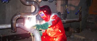
When welding galvanized pipes, the temperature in the welding zone reaches +1200 ℃. The zinc layer burns out. This metal begins to boil already at +906 ℃. That is, it turns out that at the junction of two pipes a zone without protection is formed. But these are not all the negative aspects of welding galvanized pipes.
Zinc gas is a substance harmful to humans. Once in the respiratory tract, it leads to suffocation. Therefore, welding in rooms without good ventilation is prohibited. In addition, for safety reasons, the welder must wear a respirator under the mask.
At high temperatures, zinc begins to evaporate rapidly, which leads to the formation of shells and pores inside the steel. And this reduces the quality of the junction and the strength of the junction of two galvanized pipes.
How to check the quality of the weld root?
The root is the most important type of suture. There is a key set of rules for creating a quality root weld:
A high-quality seam has no voids at the joint
- there should be no strong wind or draft, otherwise pores will form;
- The welding current should not be exceeded, otherwise the structure of the metal will be damaged;
- you need to choose the correct gap (depending on the thickness of the metal wall);
- It is preferable to use a short arc;
- When using direct current, it is advisable to prevent water from getting on the electrodes and metal.
Welding a fixed vertical joint
The weld is performed in two steps. The perimeter of the joint is conventionally divided by the vertical center line into two sections, each of which has three characteristic positions:
- ceiling (positions 1-3);
- vertical (positions 4-8);
- lower (positions 9-11).
Each section is welded from the ceiling position. Welding is carried out only with a short arc:
lmin=0.5 de, mm, where de is the diameter of the electrode.
Finish the seam in the lower position.
Welding of each section begins with a displacement of 10-20 mm from the vertical axial. The area where the seams overlap—the “lock” connection—depends on the diameter of the pipe and can be from 20 to 40 mm. The larger the pipe diameter, the longer the “lock”
The initial section of the seam is performed in the ceiling position “at an angle back” (pos. 1,2). When switching to a vertical position (positions 3-7), welding is carried out at a “forward angle”. Upon reaching position 8, the electrode is oriented at a right angle, and, having moved to the lower position, welding is again carried out at a “backwards angle”.
Before welding the second section, you need to clean the initial and final sections of the seam with a smooth transition to the gap or to the previous bead. Welding of the second section should be performed in the same way as the first.
For the root seam, an electrode with a diameter of 3 mm is used. The current strength in the ceiling position is 80-95 A. In the vertical position, it is recommended to reduce the current to 75-90 A. When welding in the lower position, the current is increased to 85-100 A.
When welding pipes with high-quality formation of the weld root without underwelding, penetration is achieved by constantly feeding the electrode into the gap. By achieving penetration inside the pipe, it is possible to obtain a seam with a convex surface, which requires subsequent mechanical stripping in the ceiling position.
Filling of pipe grooves with a wall thickness of more than 8 mm occurs unevenly. As a rule, the bottom position lags behind. To level the filling of the groove, it is necessary to additionally fuse beads in the upper part of the groove. The penultimate layers should leave an unfilled groove to a depth of no more than 2 mm.
The facing seam is welded in one or more passes.
The penultimate roller is finished so that the groove remains unfilled to a depth of 0.5-2 mm, and the base metal along the edges of the groove is melted to a width of 1/2 the diameter of the electrode.
When welding pipes with a diameter of less than 150 mm and a wall thickness of less than 6 mm, as well as in installation conditions when the power source is remote from the work site, welding is carried out at the same value of the welding current. It is recommended to select the current mode for the ceiling position, the current in which is sufficient for the lower position. When welding on the rise from the ceiling to the vertical position, to avoid excessive penetration, you should resort to intermittent formation of the seam. With this method, the arc burning process is periodically interrupted at one of the edges.
Depending on the thickness of the pipe wall, the gap and the bluntness of the edges, it is recommended to perform “strokes” welding in one of the following ways:
| 1. The arc is constantly lit on one of the edges, and interrupted after the formation of the bath - on the other. The pause between the break and ignition should be so short that the weld metal does not have time to completely crystallize and the slag does not have time to cool. |
| 2. If the metal is thick, the arc is ignited and interrupted at the same edge. It is not recommended to light an arc in the place where it just broke. Without breaking the arc, you cannot move the electrode forward during the cutting, and then return to the seam again. |