Galvanized chimney pipe: types, which is better and how to make it yourself
Hello, dear reader! Today we will consider the question of how good a galvanized pipe is for a chimney. The need for such an assessment arises every time before the owners of private houses when constructing or replacing a chimney. Let's find out all its pros and cons, how best to use it and whether it can be done with your own hands.
What is
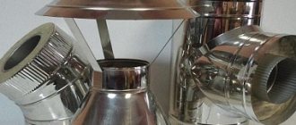
The product is a metal pipe coated with a layer of zinc (pictured).
The coating creates a protective film that protects the iron from rust for a certain period, until the zinc layer is mechanically damaged.
Material characteristics
Zinc is a metal with a melting point of 419 C.
The composition of the zinc coating includes an alloy of zinc (99.97%), aluminum, lead and other metals. The layer thickness is standardized by GOST and ranges from 10 to 60 microns.
In air, zinc is covered with a thin film of oxide, which acts as a protection for steel from corrosion.
Galvanized steel is resistant to precipitation and temperature changes.
Convenient to process, easy to bend, roll, stamp and other mechanical loads.
Can galvanized pipes be used for chimneys?
Chimneys with zinc coating are used under certain conditions.
When zinc is heated to 419°, it begins to release substances harmful to humans. Therefore, it is recommended to install outlets made of this material in smoke exhaust systems where the temperature does not exceed 350°C.
The 2009 Ministry of Emergency Situations rules prohibit the use of metal smoke removal agents for coal-fired stoves.
In addition, a single-wall galvanized outlet will burn out after one or two seasons. In practice, it is used as an outer casing in double-walled structures with insulation.
Advantages and disadvantages of galvanized pipes
Users include the following advantages of a galvanized chimney pipe:
- long-term immunity to corrosion;
- rapid heating of the chimney and, as a result, ensuring good draft;
- simple assembly method;
- a smooth surface inside the channel, which does not allow soot to linger on the walls;
- Possibility of venting through the wall of the building.
Flaws:
- short service life of a single-wall outlet;
- when cutting a product, the cut lines begin to rust after a short time;
- minor damage leads to the destruction of the protective layer;
- formation of a large amount of condensate.
Types of galvanized iron pipes
Based on the design features, two types of these products are distinguished: single-circuit and double-circuit insulated.
The first ones consist of single-wall bends. They are installed in heating devices with low temperatures or in brick chimneys.
The second ones include two outlets: an internal one made of stainless steel and an external one made of galvanized steel. An insulating agent is placed between them. They are called “sandwich” pipes and have managed to prove their effectiveness.
Life time
Galvanized outer pipe in a sandwich, when properly installed and manufactured, can last 45 years.
A single-circuit chimney will burn out quickly; its service life, depending on the intensity of use, will be one to two years.
What is better galvanized or stainless steel?
It is recommended to make the initial section of the chimney channel from the boiler, where the temperature is especially high, from stainless steel. The inner pipe of the sandwich is made from it, which allows it to be used in any smoke removal system.
Of course, this type of steel is the most durable and rust-resistant. In these parameters it is superior to galvanization. Its main drawback is its high price.
To reduce the cost of sandwiches, galvanization is used to make the casing.
Make it yourself or buy it
Making a pipe from sheet material is not an easy task. Requires certain equipment and skills. But if the length of the chimney is short, and it is straight, without bends or bends, you can do this work yourself.
In other cases, it would be wiser to purchase or order a galvanized chimney from professionals.
Selection tips and approximate price
Manufacturers offer a large selection of both single-circuit galvanized bends and sandwich pipes with a galvanized shell. There are certain parameters by which you should select elements for the chimney:
- the diameter of the boiler outlet pipe must be equal to or less than the cross-section of the chimney outlet;
- attached chimneys can have no more than three bends along the entire length of the channel.
- Manufacturers indicate the required chimney diameter for boilers in the unit’s passport;
- The wall thickness for the outer casing must be at least 0.5 mm, usually 0.55 mm is used.
The price of single-circuit galvanized steel pipes depends on the diameter and thickness of the sheet metal. A meter bend d=110 mm costs 190 rubles, and d=250 mm costs 390 rubles.
A stainless steel + galvanized sandwich of the same diameter, 0.5 mm thick and 100 cm long will cost 1,230 rubles.
Making galvanized pipes with your own hands
A special feature of a factory-made galvanized pipe is its reliable welding seam.
If you have an argon unit at home and you are a big welder, this makes a difference. Surely what you will get is not a pipe, but a feast for the eyes.
First you need to choose a galvanized sheet for the pipe. Professionals make bends with walls 0.55 mm thick. At the same time, it must be taken into account that the thinner the material, the easier it is to bend.
Required tools and materials
You will need:
- hand scissors for metal;
- mallet with a wooden striking part;
- roulette;
- square;
- metal ruler;
- pencil, preferably a construction pencil;
- pliers.
For the convenience of bending work, a simple workbench is equipped where markings are made. A metal corner (40×40 mm or more) with a length of at least 100 cm, a steel round shape of the required diameter, is attached to the table.
Cutting out the workpiece
Let's look at how to make a pipe with a cross-section of 100 mm.
Calculate the width of the workpiece:
- determine the circumference as the product of the cross section and the value of pi equal to 3.14;
- 15 mm are allocated for the bends for the connecting seam.
In total, for a 100 mm bend, a workpiece with a width of 3.14 × 100 mm + 15 mm ≈ 330 mm is cut out.
Take into account that the pipes are made slightly cone-shaped for ease of installation using the socket method. Therefore, one side measures 330 mm, the other 340 mm (in the figure).
Formation of a profile
On the cut-out workpiece, mark a fold line for a fold of 5 mm on one side, twice 5 mm each on the other.
The sheet is laid on a workbench, the edge is aligned with the corner. Using a mallet, gradually bend it at a right angle. Then the workpiece is turned over and the fold is placed on the canvas.
In the same way, a 10 mm bend is made on the other edge of the sheet, and another 5 mm wide on it.
Next, the workpiece is manually bent on the forming tube, using a mallet.
Processing the butt seam
After obtaining a round shape of the workpiece, it is placed on a round form or an additional corner, the folds are connected into a lock, tapping them along the edges with a mallet. At the narrow end of the future pipe, the folds are slightly cored. Tap the entire length of the joining seam with a mallet, compacting the folds. The seam becomes almost permanent.
Standards
There is a whole range of bends with different angles - 45, 60, 90 and 180 O. All of them are manufactured in accordance with GOST 17375-2001 from various grades of steel and meet all the requirements of reliability and strength. However, buying them can be quite difficult, especially when you live in a rural area and are far from large stores.
Standards for corner bends
GOST 17375-2001 implies the use of higher quality steel than in the manufacture of pipes, but for such diameters and for everyday tasks the material from which the pipes are made is quite sufficient. Such a 90-degree steel pipe bend carries all loads and serves no less than the main pipeline itself.
How to deal with such a difficult situation and whether it is possible to make a bend with your own hands at home from scrap materials will be discussed in this article.
Branches in polyurethane foam insulation
An outlet in polyurethane foam insulation - consists of a steel outlet, on top of which a protective casing (outlet shell) made of polyethylene or galvanized steel is placed, and the space between the outlets is filled with polyurethane foam.
The following trade names are available: pre-insulated outlet, pre-insulated outlet, thermally water-insulated outlet, steel outlet in polyurethane foam insulation.
These products are manufactured in accordance with GOST 30732-2006.
During the production process, steel pipes are welded to the steel outlet and a polyethylene (PE) or galvanized steel (ZS) protective casing is put on. To ensure uniform distribution of the heat-insulating layer of polyurethane foam (PPU), centering supports are installed between the outlet with branch pipes and the protective shell. The resulting space is filled with polyurethane foam. This manufacturing technology is called “Pipe in Pipe”.
Purpose
Bends in polyurethane foam insulation are used in the modernization and construction of heating networks through which the working medium is circulated, having the following parameters:
- ultimate pressure: 1.6 MPa;
- maximum long-term t°: +140°С;
- short-term peak t°: +150°С;
- nominal temperature range for regulating the amount of heat supplied to consumers: +70°÷ +150°С.
- 150 (-20) mm with D (diameter of the protective shell) up to 315 mm inclusive;
- 210 (-20) mm with D equal to or exceeding 400 mm.
Bends in polyurethane foam insulation are designed to change the direction of the thermal route.
In addition to the main purpose, bends in polyurethane foam insulation can be used for pumping gas, oil, and other liquid and gaseous media.
The laying of pipelines using bends can be carried out directly in the ground, in non-passable, semi-passable and through reinforced concrete channels, tunnels, as well as in ground and above-ground methods.
HDPE tapping welding - production.
Cutting steel pipe in production conditions.
Advantages
Polyurethane foam acting as a heat insulator has low thermal conductivity, which makes it possible to maintain a stable temperature of the transported media with minimal heat loss.
Table No. 1 shows the comparative characteristics of polyurethane foam and other common thermal insulation materials.
| Thermal insulator | Density degree (kg/m3) | Thermal conductivity coefficient (W/m*K) | Porosity | Service life (years) |
| Polyurethane foam (PPU) hard | 40-200 | 0,025-0,033 | closed | 30-50 |
| Mineral wool | 11-150 | 0,045-0,058 | open | 5 |
| Cork board | 220-240 | 0,035-0,060 | closed | 3 |
| Foam concrete | 250-400 | 0,025-0,035 | open | 10 |
| Styrofoam | 30-60 | 0, 037-0,050 | closed | 5-7 |
"TABLE 1" Comparison of parameters of various thermal insulation materials
As follows from the table, polyurethane foam has the best thermal conductivity coefficient and estimated service life. The proven “pipe-in-pipe” production technology and low cost of components provide this product with the most favorable price/quality ratio among competing materials.
Design
The design of bends in polyurethane foam insulation must comply with GOST 30732-2006. Below, Figure 1 shows a drawing of an outlet in polyurethane foam insulation
Figure 1. Design of an outlet in polyurethane foam insulation
1 - steel pipe; 2 - insulation made of polyurethane foam; 3 - shell; 4 - centering support; 5 - steel bend; 6 - electrical insulating tube (for pipes with a steel sheath); 7 — conductor-indicator of the UEC system (shown conditionally)
The outer diameter of the steel bend (d) must be from 32 to 1420 mm.
The outer diameter of the protective shell (D) should be from 90 to 1600 mm, α is the angle of rotation of the bend, varies from 00 to 900, L is the length of the bend arm from the end to the axis.
On bends of bends, deviations of the center lines are allowed that exceed the deviations allowed on straight sections. The thickness of the outlet insulation, measured at any point, must be at least 15 mm
For ease of installation, when applying the heat-insulating layer, bare ends are left, the length of which must be within the following limits:
Varieties
Bends in polyurethane foam insulation are divided into several types depending on the raw materials used. Depending on the use of the supporting steel pipe in the heating network, the following types of bends in polyurethane foam insulation are distinguished:
- bends with electric-welded pipes GOST 10704, 10705, 10706 in polyurethane foam insulation;
- bends with seamless hot-deformed pipes GOST 8731, 8733 in polyurethane foam insulation;
- bends with seamless cold-deformed and heat-deformed branch pipes GOST 8732, 8734 in polyurethane foam insulation;
- bends with seamless pipes for the oil refining and petrochemical industries GOST 550 in polyurethane foam insulation;
- bends with welded pipes for main gas and oil pipelines GOST 20295 in polyurethane foam insulation;
Source: https://www.teploenergoplast.ru/catalog/teplotrassa/otvody-v-ppu-izolyatsii/
Types of corner joints
The main regulatory document that regulates the welding of pipes at an angle - GOST 16037-80 - states that in addition to five methods of welding tees (crosses), there are also eight ways of joining sectors in a bend (elements in a track).
Moreover, angular coupling, which involves joining highways, both at a right angle and at an acute or obtuse angle, is realized using the following types of joints:
Docking the highway at an acute angle
- Corner connection of pipes of the same diameter, without beveled edges, with a one-sided weld. Designation according to GOST – U16. In this case, the edges of the pipes are ground down and adjusted to each other with virtually no gap, and the projection of the mating line resembles a triangle.
- Corner connection of a pipe and a fitting (branch or welding), without section, with a one-sided weld, Designation according to GOST - U17, U18. The projection of the welding joint is similar to a semicircle. The edges fit together with minimal clearance.
- Corner connection with beveled edges, one-sided seam, designated code U19. The conjugation line is similar to a sector of a circle. The edges of the lower pipe are practically not processed. The section (chamfer) is removed only from the top pipe.
- A corner connection with a beveled edge on a cylindrical miter, made with a one-sided seam (code U20). The projection of the mating line is similar to the arc sector, and the edges of the lower pipe are practically not processed.
- Angular connection to a section, on a one-sided gasket, with a ring-shaped liner placed inside the pipe. The seam is sealed from the outside and marked on the assembly drawings as U21.
Round Steel Vent Vent 90° Degree
A 90° round ventilation outlet (another name is an elbow) is designed to change the route of the ventilation duct by 90° degrees. Round cross-section bends for general ventilation are made of galvanized steel . The ventilation duct is a shaped air duct , therefore it is characterized by all the properties of round air ducts: round ventilation ducts create less air resistance compared to rectangular analogues.
Diagram of a 90° degree round vent
Symbol in the diagram:
D —product diameter, mm;
R — turning radius, mm.
Technical characteristics of round ventilation ducts AeroStar
From us you can buy high-quality ventilation ducts made of steel , which we been producing for 15 years .
find out steel bends price list.
| Diameter, mm. | Steel thickness, mm. | Area, sq. m. | Weight, kg. | Number of component segments, pcs. |
| 100 | 0,55 | 0,11 | 0,47 | 3 |
| 125 | 0,16 | 0,75 | 4 | |
| 160 | 0,25 | 1,13 | 4 | |
| 200 | 0,37 | 1,75 | 4 | |
| 250 | 0,56 | 2,86 | 4 | |
| 280 | 0,68 | 3,04 | 4 | |
| 315 | 0,74 | 3,78 | 4 | |
| 355 | 0,93 | 4,23 | 4 | |
| 400 | 1,05 | 5,80 | 4 | |
| 450 | 0,7 | 1,22 | 6,91 | 4 |
| 500 | 1,56 | 8,44 | 4 | |
| 560 | 1,88 | 10,4 | 4 | |
| 630 | 2,38 | 13,20 | 4 | |
| 710 | 3,30 | 18,20 | 4 | |
| 800 | 3,71 | 22,04 | 4 | |
| 1000 | 0,9 | 5,97 | 42,90 | 5 |
| 1250 | 9,07 | 66,80 | 5 |
The turning radius (R) of a standard elbow manufactured by us is equal to its diameter: R=D.
Manufacturing of round ventilation ducts to order
We make non-standard ventilation products to order . To buy such a product, as well as to clarify the price, you need to send a drawing of the part to us by email . Possible modifications:
- Changing the radius (R) of the product
- Changing the rotation angle (60°, 30°, 15°, etc.)
- Changing the length of the neck of the product
- Manufacturing a product with a transition function (retraction-transition)
- Manufacturing products of non-standard diameter
Connection types for round steel vent
All AeroStar round shaped air ducts a nipple connection as standard , due to the fact that the outer diameter of the shaped air ducts is smaller than the internal diameter of straight air ducts, they are simply inserted inside - which speeds up and simplifies the installation of the ventilation system. In addition, we produce shaped air ducts with other types of connections. Possible connection options:
- Nipple (the product has nipple dimensions, i.e. it is inserted into the air duct)
- Flanged
- At the request of the customer (the product is put on the air duct)
Buy round ventilation ducts made of steel
We are engaged in the sale of round ventilation ducts, both from production and from warehouse; products made of galvanized steel up to 355 diameter are always available in stock.
You can find out the price for round ventilation ducts the price list section of the website.
To place an order, find out the price and buy the necessary ventilation products just send your request to us by email [email protected] or call: (812) 313-41-15
Source: https://aerostar-spb.ru/catalog/round_ventilation/143/
Main stages of work
At the next stage, using a sheet of paper, you will need to connect a point at a distance of 30 mm from the edge with the “zero” point at the end of the pipe. Draw two lines on both sides.
Next, use a grinder to cut a piece of pipe according to the markings. In the same way, the craftsman cuts out the second piece of round pipe.
The author made a template from a plastic bottle that completely repeats the cut of the first workpiece. And using the template we cut out the connecting segment.
At the last stage, all that remains is to clean and cook everything. For more information about this method, watch the video below. This review is based on a video from the Welder DIY YouTube channel.
Source
Steel bends: products for changing the direction of the pipeline
Steel bends are products that are used to change the direction of various pipelines. They are pipe segments bent at the desired angle. They are usually carried out using special pipe bending machines and are mounted on the pipeline by butt welding. The operational scope of these parts is incredibly wide, but they are most often used in the installation of oil, gas and water supply communications.
Bends for steel pipes are made of stainless steel, alloy steel, and they can also have a protective zinc coating
Scope of use of steel bends
Let's consider the main areas in which these products are used:
- plumbing systems;
- heating communications;
- industrial highways for various purposes;
- oil and gas industry;
- chemical industry;
- pumping stations.
Such products are used for wiring communications for any purpose, however, not all of their types are suitable for certain pipelines. For example, for laying main networks, as a rule, steeply curved seamless, stamped-welded, and bent products made of stainless steel, alloyed, and galvanized bends are used. This is due to the fact that such communications have large cross-sectional dimensions and can operate at high pressure in the working environment.
Helpful information! Welded bends are used for various communications. The pressure in such pipelines does not exceed 2.5 MPa. The cross-sectional indicators in such pipelines are usually more than 1000 mm.
For household communications, steeply curved or bent types of bends are an excellent solution. And point products are very popular when installing pipelines at enterprises that produce various mineral fertilizers.
Such a part as a bend can be found on a pipeline of any type and purpose.
As mentioned above, such a product provides rotation of the structure. Bends are used not only in pipelines, but also in communications responsible for cleaning indoor air. The most popular in this case is a galvanized ventilation outlet.
Advantages of steel bends
Pipeline fittings are widely used in any installation, and steel turning parts are considered the backbone of any pipeline. Along with tees and transition elements, they play an important role in connecting communications and increasing its strength.
Let's look at the main advantages of these products:
- with the help of these products a smooth rotation of the pipeline structure is made;
- the characteristics of metal bends allow them to be used in difficult operating conditions - they have high strength characteristics and can also be operated at high pressure;
- steel products are resistant to temperature fluctuations;
- the cost of such bends is quite affordable;
- have a long service life when used in aggressive industrial conditions.
How to weld a fitting correctly
In order to perform a beautiful and reliable installation of the pipeline and weld a 90-degree bend to the pipe, you need to choose the right welding machine and electrodes. It is better to look for this information on specialized forums, where experts will be happy to tell you what electrodes and operating modes of the welding machine they use in their professional work.
Pipeline parts are welded using the butt welding method, this is when the edges fit tightly to each other. The thickness of the electrode for such work is taken to be 2-3 mm at a welding voltage of 80-110 Amps. In order for as little burnt metal as possible to get inside, the electrode must be positioned at an angle of 45 ° to the surface. It is advisable to weld round pipes in one continuous seam. After welding, you must wait until the seam has completely cooled down and beat off the slag, and only then proceed to the next seam.
In order to get beautiful and even seams, you need to fill your hand, so don’t despair if it doesn’t work right away. Practice first by welding just small pieces of pipe. And only after this should you proceed directly to welding the pipeline.
Source
Indications for use
Gas pipe welding
Electric arc, argon arc or gas welding without beveled edges begins with adjusting the ends. The maximum gap between the pipes, in this case, is 1.5 millimeters, and the minimum is 0.5 millimeters. Moreover, this technique is used only on pipes with a wall thickness of 1 to 6 millimeters. The process itself begins with tacking the corner joint with spot welds, followed by straightening the position of the pipes and circumferentially welding the joint from the outside.
Angular mating with a one-sided end involves the formation of a chamfer at an angle of 50 degrees. A double-sided section involves the formation of two chamfers at an angle of 30 degrees. The gap between the edges in the first case is 1-2 millimeters, and in the second case 2-5 millimeters. That is, you can practically not worry about the accuracy of the ends. The wall thickness of pipes joined in this way ranges from 2 to 20 millimeters.
Angular mating with beveled edges and section involves joining pipes with a wall thickness of 6 to 60 millimeters. In this case, the width of the section ranges from 18 to 48 millimeters. Of course, such dimensions require a special technique for filling the weld pool.
Precision cutting devices
Among branded devices that could be used in everyday life to make cuts at an angle, you can pay attention to Italian-made equipment.
The Mini Cut band saw is a small-sized device with manual clamping, for working not only with pipes, but also with angles, rods, and profile elements.
The machine supports setting the cutting angle from 0 to 45º. The procedure is carried out using a tape at a speed of 45 reciprocating movements per minute. The device is equipped with a 370 W electric motor, which is powered from a household network. The maximum permissible diameter of a round pipe to be cut is 65 mm.
On an industrial scale, numerous installations with electromechanical and electrical drives have been developed for pipe cutting. Technically sophisticated devices allow high-precision thermal, oxygen and plasma cutting:
Welding pipelines at specified angles. Calculation and marking of pipes during welding work
The magnitude of the angle α formed by the intersection of two pipes of different diameters when welding them with a tee
Picture 1
| Diameter of the smaller pipe d, mm | Diameter of the larger pipe D, mm | |||||||||||||||||||||||||||||||||||||||||||||||||||||||||||||||||||||||||||||||||||||||||||||||||||
| 102 | 127 | 152 | 203 | 254 | 305 | 356 | 406 | 457 | 508 | 559 | 610 | 660 | 711 | 762 | 813 | 864 | 914 | 965 | 1016 | |||||||||||||||||||||||||||||||||||||||||||||||||||||||||||||||||||||||||||||||||
| 76 | 97 | 74 | 60 | 44 | 35 | 29 | 25 | 22 | 19 | 17 | 16 | 14 | 13 | 12 | 11 | 11 | 10 | 10 | 9 | 9 | ||||||||||||||||||||||||||||||||||||||||||||||||||||||||||||||||||||||||||||||||
| 102 | 106 | 83 | 60 | 47 | 39 | 33 | 29 | 26 | 23 | 21 | 19 | 18 | 16 | 15 | 14 | 14 | 13 | 12 | 11 | |||||||||||||||||||||||||||||||||||||||||||||||||||||||||||||||||||||||||||||||||
| 127 | 113 | 77 | 60 | 49 | 42 | 36 | 32 | 29 | 26 | 24 | 22 | 20 | 19 | 18 | 17 | 16 | 15 | 14 | ||||||||||||||||||||||||||||||||||||||||||||||||||||||||||||||||||||||||||||||||||
| 152 | 97 | 74 | 60 | 51 | 44 | 39 | 35 | 32 | 29 | 27 | 25 | 23 | 22 | 20 | 19 | 18 | 17 | |||||||||||||||||||||||||||||||||||||||||||||||||||||||||||||||||||||||||||||||||||
| 203 | 106 | 84 | 70 | 60 | 53 | 47 | 43 | 39 | 36 | 33 | 31 | 29 | 27 | 26 | 24 | 23 | ||||||||||||||||||||||||||||||||||||||||||||||||||||||||||||||||||||||||||||||||||||
| 254 | 113 | 91 | 77 | 67 | 60 | 54 | 49 | 45 | 42 | 39 | 36 | 34 | 32 | 31 | 29 | |||||||||||||||||||||||||||||||||||||||||||||||||||||||||||||||||||||||||||||||||||||
| 305 | 118 | 97 | 84 | 74 | 66 | 60 | 55 | 51 | 47 | 44 | 41 | 39 | 37 | 35 | ||||||||||||||||||||||||||||||||||||||||||||||||||||||||||||||||||||||||||||||||||||||
| 356 | 122 | 102 | 89 | 79 | 71 | 65 | 60 | 56 | 52 | 49 | 46 | 43 | 41 | |||||||||||||||||||||||||||||||||||||||||||||||||||||||||||||||||||||||||||||||||||||||
| 406 | 125 | 106 | 93 | 84 | 76 | 70 | 64 | 60 | 56 | 53 | 50 | 47 | ||||||||||||||||||||||||||||||||||||||||||||||||||||||||||||||||||||||||||||||||||||||||
| 457 | 128 | 110 | 97 | 88 | 80 | 74 | 69 | 64 | 60 | 57 | 53 | |||||||||||||||||||||||||||||||||||||||||||||||||||||||||||||||||||||||||||||||||||||||||
| 508 | 131 | 113 | 101 | 91 | 84 | 77 | 72 | 68 | 64 | 60 | ||||||||||||||||||||||||||||||||||||||||||||||||||||||||||||||||||||||||||||||||||||||||||
| 559 | 133 | 116 | 104 | 94 | 87 | 81 | 75 | 71 | 67 | |||||||||||||||||||||||||||||||||||||||||||||||||||||||||||||||||||||||||||||||||||||||||||
| 610 | 135 | 118 | 106 | 97 | 90 | 84 | 78 | 74 | ||||||||||||||||||||||||||||||||||||||||||||||||||||||||||||||||||||||||||||||||||||||||||||
| 660 | 136 | 120 | 109 | 100 | 92 | 86 | 81 | |||||||||||||||||||||||||||||||||||||||||||||||||||||||||||||||||||||||||||||||||||||||||||||
| 711 | 138 | 122 | 111 | 102 | 95 | 89 | ||||||||||||||||||||||||||||||||||||||||||||||||||||||||||||||||||||||||||||||||||||||||||||||
| 762 | 139 | 124 | 113 | 104 | 97 | |||||||||||||||||||||||||||||||||||||||||||||||||||||||||||||||||||||||||||||||||||||||||||||||
| 813 | 140 | 125 | 115 | 106 | ||||||||||||||||||||||||||||||||||||||||||||||||||||||||||||||||||||||||||||||||||||||||||||||||
| 864 | 142 | 127 | 116 | |||||||||||||||||||||||||||||||||||||||||||||||||||||||||||||||||||||||||||||||||||||||||||||||||
| 914 | 143 | 128 | ||||||||||||||||||||||||||||||||||||||||||||||||||||||||||||||||||||||||||||||||||||||||||||||||||
| 965 | 144 | |||||||||||||||||||||||||||||||||||||||||||||||||||||||||||||||||||||||||||||||||||||||||||||||||||
When welding pipes with diameters D = 508 mm and d = 254 mm with a tee, the angle formed by the intersection of two pipes will be 60°.
Length of the arc by the intersection of two pipes of different diameters when welding them with a tee (in mm)
Figure 2
| Diameter of the smaller pipe d, mm | Diameter of the larger pipe D, mm | |||||||||||||||||||||||||||||||||||||||||||||||||||||||||||||||||||||||||||||||||||||||||||||||||||
| 102 | 127 | 152 | 203 | 254 | 305 | 356 | 406 | 457 | 508 | 559 | 610 | 660 | 711 | 762 | 813 | 864 | 914 | 965 | 1016 | |||||||||||||||||||||||||||||||||||||||||||||||||||||||||||||||||||||||||||||||||
| 76 | 86 | 82 | 80 | 78 | 77 | 77 | 77 | 77 | 77 | 77 | 77 | 77 | 77 | 77 | 77 | 77 | 77 | 77 | 77 | 77 | ||||||||||||||||||||||||||||||||||||||||||||||||||||||||||||||||||||||||||||||||
| 102 | 160 | 118 | 110 | 106 | 104 | 104 | 103 | 103 | 103 | 102 | 102 | 102 | 102 | 102 | 102 | 102 | 102 | 102 | 102 | 102 | ||||||||||||||||||||||||||||||||||||||||||||||||||||||||||||||||||||||||||||||||
| 127 | 200 | 150 | 137 | 133 | 130 | 130 | 129 | 129 | 129 | 128 | 128 | 128 | 128 | 128 | 128 | 128 | 128 | 128 | 128 | |||||||||||||||||||||||||||||||||||||||||||||||||||||||||||||||||||||||||||||||||
| 152 | 239 | 172 | 164 | 160 | 158 | 156 | 156 | 156 | 156 | 155 | 155 | 155 | 154 | 154 | 153 | 153 | 153 | 153 | ||||||||||||||||||||||||||||||||||||||||||||||||||||||||||||||||||||||||||||||||||
| 203 | 319 | 235 | 223 | 217 | 213 | 211 | 208 | 208 | 207 | 207 | 206 | 206 | 206 | 205 | 205 | 205 | 205 | |||||||||||||||||||||||||||||||||||||||||||||||||||||||||||||||||||||||||||||||||||
| 254 | 399 | 301 | 282 | 273 | 267 | 266 | 263 | 261 | 261 | 261 | 259 | 258 | 257 | 257 | 257 | 257 | ||||||||||||||||||||||||||||||||||||||||||||||||||||||||||||||||||||||||||||||||||||
| 305 | 479 | 366 | 344 | 335 | 328 | 322 | 320 | 318 | 316 | 314 | 312 | 311 | 311 | 311 | 310 | |||||||||||||||||||||||||||||||||||||||||||||||||||||||||||||||||||||||||||||||||||||
| 356 | 559 | 433 | 407 | 395 | 385 | 378 | 376 | 374 | 372 | 370 | 368 | 366 | 365 | 364 | ||||||||||||||||||||||||||||||||||||||||||||||||||||||||||||||||||||||||||||||||||||||
| 406 | 638 | 499 | 470 | 454 | 447 | 438 | 436 | 434 | 426 | 424 | 422 | 420 | 418 | |||||||||||||||||||||||||||||||||||||||||||||||||||||||||||||||||||||||||||||||||||||||
| 457 | 718 | 567 | 536 | 516 | 507 | 497 | 492 | 487 | 482 | 478 | 474 | 470 | ||||||||||||||||||||||||||||||||||||||||||||||||||||||||||||||||||||||||||||||||||||||||
| 508 | 798 | 639 | 601 | 582 | 565 | 557 | 549 | 544 | 540 | 536 | 532 | |||||||||||||||||||||||||||||||||||||||||||||||||||||||||||||||||||||||||||||||||||||||||
| 559 | 878 | 708 | 669 | 645 | 625 | 615 | 607 | 602 | 598 | 594 | ||||||||||||||||||||||||||||||||||||||||||||||||||||||||||||||||||||||||||||||||||||||||||
| 610 | 958 | 778 | 732 | 705 | 688 | 678 | 670 | 663 | 656 | |||||||||||||||||||||||||||||||||||||||||||||||||||||||||||||||||||||||||||||||||||||||||||
| 660 | 1037 | 844 | 798 | 773 | 754 | 734 | 724 | 718 | ||||||||||||||||||||||||||||||||||||||||||||||||||||||||||||||||||||||||||||||||||||||||||||
| 711 | 1117 | 918 | 865 | 837 | 814 | 800 | 789 | |||||||||||||||||||||||||||||||||||||||||||||||||||||||||||||||||||||||||||||||||||||||||||||
| 762 | 1197 | 986 | 935 | 902 | 876 | 860 | ||||||||||||||||||||||||||||||||||||||||||||||||||||||||||||||||||||||||||||||||||||||||||||||
| 813 | 1277 | 1055 | 997 | 969 | 940 | |||||||||||||||||||||||||||||||||||||||||||||||||||||||||||||||||||||||||||||||||||||||||||||||
| 864 | 1357 | 1133 | 1070 | 1028 | ||||||||||||||||||||||||||||||||||||||||||||||||||||||||||||||||||||||||||||||||||||||||||||||||
| 914 | 1436 | 1204 | 1135 | |||||||||||||||||||||||||||||||||||||||||||||||||||||||||||||||||||||||||||||||||||||||||||||||||
| 965 | 1516 | 1277 | ||||||||||||||||||||||||||||||||||||||||||||||||||||||||||||||||||||||||||||||||||||||||||||||||||
| 1016 | 1596 | |||||||||||||||||||||||||||||||||||||||||||||||||||||||||||||||||||||||||||||||||||||||||||||||||||
Example: When welding pipes with diameters D = 508 mm and d = 254 mm with a tee, the arc length will be 266 mm. The method of setting aside the value in when marking a hole in a large-diameter pipe is visible in the drawing.
