These technical specifications apply to steel pipeline fittings: steel flanged shut-off valves models 15s22nzh, 15s65nzh, flanged check valves models 19s53nzh, steel flanged and welded ball valves models KSSh (hereinafter referred to as “devices or products” ), intended for shutting off, automatically shutting off the backflow flow of the working medium (steam or water) in pipelines used in chemical, oil refining, petrochemical and other related industries.
These technical specifications apply to valves of the following models:
— steel shut-off valves, models 15s22nzh, DN from 15 to 400 mm, PN 40; 15s65nzh, DN from 15 to 400 mm, RN 16 (GOST 3326, GOST 9697);
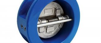
— check valves flanged models 19s53nzh, DN from 50 to 200 mm, PN 40 (GOST 27477, GOST 53671);
— steel ball valves, flanged and welded, models KSSH DN from 50 to 300 mm, PN 25; DN from 15 to 50 mm, PN 40; DN from 50 to 300 mm, RN 25, DN from 15 to 50 mm, PN 40 (GOST 21345, GOST 28343).
The products are used in climatic modifications U, UHL, T, placement categories 1,2,3,4 according to GOST 15150.
Example of an entry when ordering products:
“Steel shut-off valve model 15s22nzh-15
TU 3742-001-ХХХХХХ-2015" (where 15 is the nominal diameter).
1.1. Products must comply with the requirements of GOST R 53672, GOST 21345, GOST 28343, GOST R 53671, these technical conditions, a set of design documentation and regulatory documents for a specific type or design, approved in the prescribed manner. Devices must be manufactured according to working drawings approved in the prescribed manner.
1.1.1. Check valves
Check valves must comply with the requirements of GOST 27477, GOST 53671.
Products exported, including to countries with tropical climates, must additionally comply with the requirements of GOST 26304.
Manufacturability requirements
Products must be sealed against the external environment using the control method specified in the design documentation.
The design documentation must indicate the installation position of the product.
Check valves should begin to open when the pressure drop is no more than 0.03 MPa and return to their original state (close) when the medium stops moving in the forward direction. The actual minimum value of the pressure drop, the start of opening of check valves and check valves, is determined when testing prototypes.
What is it and what is it for?
A shut-off valve (OK) is needed to block the movement of the working medium in pipelines during emergencies. These include:
- leaks and flooding in the event of malfunctions in pipes and other elements of the system;
- stopping the pumping unit, which resulted in the formation of a reverse flow of liquid;
- a decrease or increase in pressure in the network with a certain deviation from the norm;
- depressurization of the main components of the pipeline due to temperature changes or ground movements.
Sometimes a cut-off device is necessary due to the peculiarities of the technological process.
The photo shows different types of shut-off valves:
Specification of parts of unbalanced throttle assembly
| № | Name of components |
| 1 | Frame |
| 2 | Clip |
| 3 | Slip-on flange |
| 4 | Threaded flange |
| 5 | Stuffing box |
| 6 | Housing gasket |
| 7 | Saddle |
| 8 | Plunger |
| 9 | Sleeve |
| 10 | Stock |
| 11 | Books |
| 12 | Seat gasket |
Purpose and scope of application
The main area of application of the cut-off device is filtration and purification systems for water. Errors in the installation of the treatment pipeline, exceeding the service life of its consumables, sudden changes in fluid pressure and other similar manifestations lead to failure of the entire system as a whole and additional financial costs. Equipping with a shut-off unit ensures safe and efficient operation of the structure and increases its service life. Enterprises in the industrial, chemical, and housing and communal services sectors also purchase and use such devices.
Methods for marking fittings
Rules for marking shut-off valves:
- imprint – on the body of the product;
- data on the characteristics of the model - from the front side;
- manufacturer's information is on the back wall.
Actually, the application process is carried out using one of three methods - stamping, branding or engraving. All 3 approaches involve deformation of the surface material with different levels of change.
Stamping is a durable way to mark shutoff valves. The designations made with its help have the service life of the structures themselves. At the same time, the quality of the print also remains high.
Branding is one of the most technologically complex methods of marking shut-off valves . Uses an electric spark pencil for marking. A rather expensive surface treatment format, therefore it is rarely used.
Engraving is one of the first methods of marking surfaces. Uses cutters (punch, milling cutter, graver), takes a minimum of time, and lasts for a fairly long period of time.
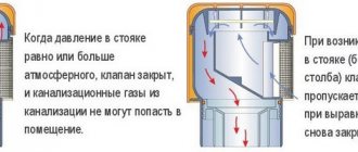
Principle of operation
A shut-off valve is often called an anti-flood, meaning its main purpose is to prevent liquid from flowing out of the pipeline.
The valve is designed in such a way that upon a manual command from personnel, a signal from a sensor or other element, or movement of the medium in a direction not provided for by the design, the shut-off device is quickly activated and the device cuts off the passage of the working medium. A characteristic feature of the device is its speed, usually provided by the actuation of a spring or other mechanism to close the valve.
For example, in a disposable valve, the liquid entering the device acts on a silicone gasket. Under the influence of moisture, it grows in volume and lifts the shutter of the locking mechanism. It blocks the channel and stops the movement of the medium. The disposable device is discarded and another valve is installed in its place. Since leaks do not happen often, the costs of such a valve are not comparable to the costs of repairing an apartment after a flood.
Examples of fittings markings with explanation of symbols
LLC NPO "SpetsNefteMash" is a serious, responsible, experienced representative of the market of manufacturers of valve products. We pay a lot of attention to the labeling of shut-off valves and always strive to make the choice of products much easier for the buyer. For clarity and understanding of the essence of the valve marking designations, we offer several “decodings” of the formulas of the products presented in our catalog.
- 30nzh541nzh. The designation is deciphered as follows:
- 30 – valve;
- nzh – stainless steel body;
- 5 – mechanical drive;
- 41 – issue registration number;
- NZ – stainless steel sealing surfaces.
- Products of the 32с908р series, where:
- 32 – rotary disk type shutter;
- c – valve surfaces made of steel (carbon);
- 9 – type of drive (in this case indicates the production of shut-off valves with electric drive);
- 08 – model registration number;
- r – rubber seals.
- 19s63nzh means that in front of you:
- check valve with sealed valve (19);
- in a carbon steel housing (c);
- issued under registration number 63;
- with steel seals (stainless steel, designation NZ).
Our shut-off valves factory ensures that the buyer’s choice is always correct. In addition, high-quality marking of fittings determines the simplicity and convenience of its storage, operation, timely replacement or renewal. We offer products with high-quality prints and good characteristics for equipping various piping systems and are constantly working to increase the awareness of our customers.
Types and designs
Today's market for pipeline fittings presents a wide variety of shut-off type devices, depending on the use and design features; their modifications are constantly appearing.
Based on functionality and body types, shut-off valves are divided into:
- checkpoints;
- corner;
- double-saddle and single-saddle.
Conventional pass-through devices are installed in networks with one-way traffic.
The latter can withstand high pressure and hydrowave shocks.
Devices of the third type produce one-way or two-way blocking of the flow.
Based on the types of locking devices, valves are divided into spring and lever-weight valves.
The solenoid valve operates by generating an electromagnetic field within it, which opens or closes the locking mechanism. This process is carried out by special latches: they press on the springs or release them, actuating the valve.
GOST 3326-86 Shut-off valves, check valves and gates. Construction lengths.
SHUT-OFF VALVES, CHECK VALVES AND VALVES
CONSTRUCTION LENGTHS
GOST 3326-86
USSR STATE COMMITTEE ON STANDARDS
| UDC 621.646.2+621.646.248: 006.354 SHUT-OFF VALVES, CHECK VALVES AND VALVES Construction lengths Stop valves, check lift and swing valves. Overall dimensions | Group G18 GOST 3326-86 Instead of GOST 3326-69 |
OKP 37 0000
By Resolution of the State Committee of Standards of the Council of Ministers of the USSR No. 110 of January 27, 1971, the introduction date was established
from 01.07.87
Failure to comply with the standard is punishable by law
1. This standard applies to industrial pipeline fittings for general industrial use and establishes the construction lengths:
Flanged, coupling and welded shut-off valves for nominal pressure Ru from 0.63 to 80 MPa (from 6.3 to 800 kgf/cm²) and nominal bore from 3 to 400 mm; Flanged, coupling and welded check valves for nominal pressure Ru from 0.63 to 32 MPa (from 6.3 to 160 kgf/cm²) and nominal bore from 10 to 400 mm; Check flanged and welded valves for nominal pressure PN from 0.63 MPa to 16 MPa (from 6.3 to 160 kgf/cm²) and nominal bore DN from 40 to 1400 mm. The construction lengths of shut-off valves, valves and check valves for welding are established without taking into account the length of the welded pipes. The standard does not apply to diaphragm valves, lined valves, with an electromagnetic drive, for special purposes and for nuclear power plants. The standard complies with ST SEV 2131-80 regarding the rules for determining and maximum deviations of construction lengths, ST SEV 2132-80, ST SEV 2133-80, ST SEV 2137-80, ST SEV 2138-80, ST SEV 3249-81, ST SEV 3251 -81 in terms of construction length dimensions (see reference appendix). 2.Terms and definitions - according to GOST 24856-81.
Note. The construction lengths of valves, lift check valves and rotary check valves correspond to the construction lengths indicated in the tables of this standard, respectively, for shut-off valves, check valves and check valves.
3. The construction lengths of cast straight-through and angle flanged shut-off valves and check valves made of gray and ductile iron and steel with the cover fastened to bolts (studs) must correspond to those indicated in the drawing. 1 and in table. 1.
| Shut-off valves and check valves through passage | Shut-off valves and angle check valves |
Table 1
mm
| Conditional passage Dy | Construction lengths | |||||||||
| L | L1 | L | L1 | L | L1 | L | L1 | L | L1 | |
| Valves | ||||||||||
| checkpoints | corner | checkpoints | corner | checkpoints | corner | checkpoints | corner | checkpoints | corner | |
| Material | ||||||||||
| Gray cast iron | Malleable iron | Steel | ||||||||
| Conditional pressure Ru, MPa (kgf/cm1) | ||||||||||
| 0,63-1,6(6,3-16) | 1,6-4(16-40) | 1,6-4(16-40) | 6,3-16(63-160) | 20-32(200-320) | ||||||
| 10 15 20 25 32 40 50 65 80 100 125 150 200 250 300 350 400 | 120 130 150 160 180 200 230 290 310 350 400 480 600 730 850 980 1100 | 85 90 95 100 105 115 125 145 155 175 200 225 275 325 375 425 475 | 120 130 150 160 180 200 230 290 310 — — — — — — — — | 85 90 95 100 105 115 125 145 155 — — — — — — — — | 120 130 150 160 180 200 230 290 310 350 400 480 600 730 850 980 1100 | 85 90 95 100 105 115 125 145 155 175 200 225 275 325 375 425 475 | 210 210 230 230 260 260 300 340 380 430 500 550 650 — — — — | 105 105 115 115 130 130 150 170 190 215 250 275 325 — — — — | 230 230 260 260 300 300 350 400 450 520 600 700 800 — — — — | 115 115 130 130 150 150 175 200 225 260 300 |
| 350 400 — — — — | ||||||||||
4. The construction lengths of stamped and stamped-welded steel straight-through flanged shut-off valves must correspond to those indicated in Fig. 2 and in table. 2
Damn.2
table 2
| Conditional passage Dy | Construction length L | |
| Conditional pressure Ru, MPa (kgf/cm²) | ||
| 1,0-4,0 (10-40) | 6.3 and 10.0 (63 and 100) | |
| 15 | 130 | 175 |
| 20 | 150 | 190 |
| 25 | 160 | 200 |
| 32 | 180 | 210 |
| 40 | 200 | 225 |
| 50 | 230 | — |
| 65 | 290 | — |
| 80 | 310 | — |
| 100 | 350 | — |
| 125 | 400 | — |
| 150 | 480 | — |
5. The construction lengths of steel corner forged or stamped shut-off valves with threaded flanges for a lens seal must correspond to those indicated in drawing 3 and table 3.
Crap. 3
Table 3
| Conditional passage Dy | Construction length L | ||
| Conditional pressure Ru, MPa (kgf/cm²) | |||
| 32,0 (320) | 40,0 (400) | 80,0 (800) | |
| 3 | 60 | 60 | — |
| 6 | 60 | 60 | 85 |
| 10 | 85 | 85 | 85 |
| 15 | 95 | 95 | 95 |
| 25 | 110 | 110 | 120 |
| 32 | 120 | 120 | 150 |
| 40 | 150 | 150 | — |
| 50 | 170 | 200 | — |
| 65 | 200 | 220 | — |
| 80 | 235 | 250 | — |
| 100 | 290 | 290 | — |
| 125 | 290 | 330 | — |
| 150 | 360 | — | — |
| 200 | 435 | 520 | — |
6. The construction lengths of cast-through shut-off valves and check valves made of gray and ductile iron, flanged with a cover on a thread and coupling with a cover on a thread or bolts (studs) must correspond to those indicated in Fig. 4-6 and in table.
| Shut-off valve, straight through, flanged with threaded cover | Straight-through flanged check valve with threaded cover |
| Damn.4 | |
| Gate valve, straight-through coupling, with threaded cover | Gate valve, straight-through coupling, with threaded cover |
| Damn.5 | |
| Straight-through coupling shut-off valve with a cover on bolts (studs) | Straight-through coupling check valve with a cover on bolts (studs) |
| Damn.6 | |
Table 4
mm
| Conditional passage Dy | Construction length L | |||
| Pipeline connection | ||||
| coupling | flanged | |||
| Material | ||||
| Gray cast iron | Malleable iron | Gray cast iron | Malleable iron | |
| Conditional pressure Py, MPa (kgf/cm²) | ||||
| 1,0-1,6 (10-16) | 1,6 (16) | 1,0-1,6 (10-16) | 1,6-2,5 (16-25) | |
| With screw cap | ||||
| 15 20 25 32 40 50 80 65 80 | 90 100 120 140 170 200 — 260 290 | 90 100 120 140 170 200 250 | — — 120 140 170 200 — | — 120 120 140 170 200 — |
| With a cover on bolts (studs) | ||||
| 260 290 | 210 250 | — — | — — | |
7. The construction lengths of cast and stamped steel globe valves and check valves for welding must correspond to those indicated in Fig. 7 and in table. 5.
Damn.7
| Pass sent by Dy | Construction length L | ||
| Conditional pressure Ru, MPa (kgf/cm²) | |||
| 2,5—4 (25-40) | 6,3-16 (63-160) | 20** and 25** (200 and 250) | |
| 10 15 20 25 32 40 50 65 80 100 125 150 200 250 300 350 | — 130 150 160 180 200 230 290 310 350 400 480 600 730 850 980 | 160 175 190 200 210 225 300 340 380 430 500 550 650 790* _ — | 160 160 160 160 230 230 300 400 450 520 600 700 800 — — — |
*Only for Ru = 6.3 MPa (63 kgf/cm²). **Only for shut-off valves
8. The construction lengths of steel flanged check valves with the axis of the shut-off body located on the seat inserted into the pipe must correspond to those indicated in Fig. 8 and in table. 6.
Damn.8
Table 6
| Conditional passage Dy | Construction length L |
| Conditional pressure Ru, MPa (kgf/cm²) | |
| 4,0 (40) | |
| 50 80 100 150 200 | 150 190 215 275 375 |
9. The construction lengths of cast flanged check valves made of gray cast iron and steel and steel for welding with the location of the axis of rotation of the shut-off body outside the flow section must correspond to those indicated in Fig. 9 and 10 and in table. 7.
| Damn.9 | Damn.10 |
Table 7
| Conditional passage, Dy | Construction length L | ||||
| Material | |||||
| Gray cast iron | Steel | ||||
| Pipeline connection | |||||
| flanged | under, welding | ||||
| Conditional pressure Ru, MPa (kgf/cm²) | |||||
| 0,63-1,6 (6,3-16) | 2,5-4 (25-40) | 6,3-16 (63-160) | 2,5-4 (25-40) | 6,3—16 (63—160)* | |
| 40 50 65 80 100 125 150 200 250 300 350 400 500 600 700 800 1000 1200 1400 | 200 230 290 310 350 400 460 500 600 — — — — — — — — — — | 200 230 290 310 350 400 480 550 650 750 850 950 1150 1350 — 1850 2250 — — | 260 300 340 380 430 500 550 650 775 900 1025 1150 1140 — — — — — — | — 230 290 310 350 400 480 550 650 750 850 950 1150 1350 1450* 1850* 2250* 2500* 2800* | — 300 — 380 430 — 560 650 — 900 — 1150 1400 — — — — — — |
* Only for gas and oil pipelines 10. The installation of the construction lengths L and L1 of flanged shut-off valves and check valves and gates, depending on the design of the sealing surfaces of the flanges, must correspond to those indicated in the table. 8.
Table 8
| Design of flange sealing surfaces | Setting construction lengths L and L1 | |
| Valves | ||
| checkpoints | corner | |
| With connecting lug | ||
| With ledge | ||
| With a depression | ||
| With a spike | ||
| With groove | ||
| Under the lens spacer | — | |
| For oval gasket | ||
11. Maximum deviations of the construction lengths of flanged and welded fittings must comply with the standards given in Table 9
Table 9
| Limit deviations | ||
| Face-to-face length L or L1 | for flanged fittings | for welding fittings |
| Up to 200 St. 200 » 300 » 300 » 400 » 400 » 500 » 500 » 600 » 600 » 900 » 900 » 1200 » 1200 » 1500 » 1500 | ±1,0 ±1,5 ±2,0 ±2,5 ±3,0 ±3,5 ±4,0 ±5,0 ±7,0 | ±2,0 ±3,0 ±4,0 ±5,0 ±6,0 ±7,0 ±8,0 ±10,0 ±14,0 |
12. Maximum deviations of construction lengths and coupling shut-off and check valves must comply with the standards given in table. 10.
| Face-to-face length L or L1 | Limit deviations |
| Up to 100 St.100 » 200 St.200 | +1,0 -1,5 +1,0 -2,0 +1,5 -2,0 |
13. Maximum deviations of the construction lengths of steel angular forged or stamped shut-off valves with threaded flanges for a lens seal for nominal pressure Ru 32, 40 and 80 MPa (320, 400 and 800 kgf/cm2) (Figure 3 and Table 3) - ± IT 14 according to GOST 25346-82. 14. Conditional passages DN - according to ST SEV 254-76. 15. Conditional pressure Ru - according to GOST 356-80. 16. Connecting dimensions of flanges - according to GOST 12815-80. 17. Coupling ends - according to GOST 6527-68.
Differences
Cut-off devices are also distinguished by the method of control. Automatic valves can be triggered by the working medium itself or based on sensor readings if any abnormal changes occur in the pipeline.
Manual control involves direct action on the locking mechanism by the operator. This is done by turning a wheel or pressing a button. Shut-off valves can be adjustable or unregulated by design, with a gland or bellows seal.
Specification of parts of the unloaded throttle assembly
| № | Name of components |
| 1 | Frame |
| 2 | Clip |
| 3 | Slip-on flange |
| 4 | Threaded flange |
| 5 | Stuffing box |
| 6 | Housing gasket |
| 7 | Saddle |
| 8 | Plunger |
| 9 | Sleeve |
| 10 | Stock |
| 11 | Books |
| 12 | Seal |
| 13 | Housing gasket |
Tips for choosing
When choosing, first of all, you need to clearly define what tasks the device will solve.
The main selection options will determine the contents of the pipeline.
Next, the operating pressure and temperature conditions of the transported medium are important.
The device must have the highest possible response speed.
All the most important information about the performance of the unit is on the product label; please read it carefully. The first two digits indicate the type of fittings 22,24 - shut-off valves.
Rules for marking fittings
Marking of fittings is a regulatory measure and must be carried out in accordance with the norms and regulations of Russian state standards. In accordance with the latter, the designations of shut-off valves are formed into a table and include numbers + letters. Order of marks:
- The first 2 digits of the row indicate the class, type, type of product;
- letters after the first 2 digits – material of the main components (body, cover);
- 1–2 numbers followed by letters – registration number (if there are 3, then the first is the type of drive used);
- 2 “closing” letters indicate the material design of the surfaces;
- the last letters indicate the design assembly option.
According to GOST, application is carried out at the last stage of its manufacture. Important condition: the impression is made upon completion of production, but before testing. This approach makes it possible to control samples rejected after a control assessment in order to promptly eliminate defects and transfer the products for production and sale.
The high quality of the marking imprint is a reputational factor, a sign of the seriousness of the manufacturer and its responsible approach to the quality of its product range. Therefore, the marking process is entrusted exclusively to specialists with appropriate training. It is important to have the skills to work with specialized equipment used for marking shut-off valves.