In this article we will try to understand what oil pipes are, which pipes are used at different stages of oil production and refining, and by what standards they are manufactured.
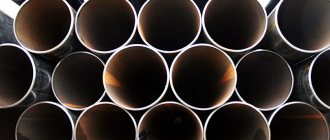
This is how many people imagine the scope of their application
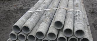
And this is how she often looks in reality
Pipes that can be called oil pipes include two large categories of very, very different products:
- Oil field pipes;
- Pipes for oil transportation.
The first category, in turn, includes several more subspecies; Each of them has its own standards.
This:
- Casing;
- Drilling;
- Pump and compressor.
Let's start with commercial ones.
Oil pipes for pumping oil and petroleum products
Fiberglass pipelines produced by SAFIT are designed for transporting multiphase oil and produced water, as well as corrosive media containing hydrogen sulfide, carbon dioxide, oxygen, acids, alkalis, and mechanical impurities.
SAFIT pipes are widely used in the oil and gas industry, when working in conditions of moving soils, flowing swamps and low average annual temperatures. Since 1996, fiberglass pipes have been used at more than 200 oil production wells and oil gathering sites of LUKOIL Western Siberia, Surgutneftegaz, Tatneft, Komineft.
increases the service life of pipelines by 5-8 times, eliminates the use of anti-corrosion protective agents, reduces the weight of the pipeline by 4-8 times, and eliminates the use of welding. The pipes are made by winding glass roving, pre-impregnated with an epoxy binder, followed by heat treatment.
Pipeline systems are designed for transporting hydrocarbons, including crude oil, diesel fuel, condensate, and reagents. The service life of oil pipes is greatly influenced by the natural and physical and chemical conditions in which the pipes operate: elevated temperatures of liquids, high flow rates, the presence of corrosive environments: hydrogen sulfide (H2S), carbon dioxide (CO2), chlorides (NaCl), salts and alkalis used in well treatment.
Pipe design
Butt joint
Joint assembly
Innovative technologies
- A special sealing layer with a specific elongation of up to 500%.
- A unique powerful bandage provides special protection against caisson and abrasive influences from the working environment.
- The socket-nipple key connection is reinforced by two rings connected to the plastic using a mechanical piercing method, ensuring equal strength of the connection nodes and the pipe wall.
Presentation Questionnaire
Unique advantages
- Service life more than 30 years.
- Operating temperature range from -50 to +50 °C. Low thermal conductivity coefficient.
- Simplicity and high speed of multiple installation and dismantling operations. Does not require welding.
- Low weight of the structure with high strength characteristics to bending, torsional and impact loads.
- Resistance to aggressive media - formation waters, alkalis, acids, gas condensate. Does not become overgrown with salts and other deposits.
- Water resistance is 30% lower than that of metal pipes.
- They do not require the use of electrical or chemical protection. They do not require insulation and associated costs.
Application for water drinking wells
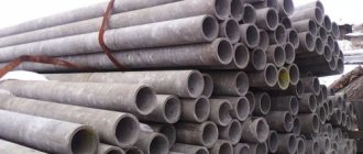
When constructing water wells, plastic, steel and asbestos-cement parts are used. The most popular due to their easy installation and low price are plastic pipes made of PVC and PE. Special equipment is used to drill such wells. Well casing occurs after drilling. The joining of individual elements in such columns occurs thanks to threaded connections.
Important! The diameter of the well and casing structure is selected based on the specific case, depending on what source productivity is required. The cross-section of the column must be such that a pumping device can be placed in it. The lower sections of the structure must be mounted from perforated pipes.
It is impossible to construct a drinking well without a casing
Although metal and asbestos-cement parts are suitable for installing water wells, their use has certain disadvantages.
Pipes are manufactured in accordance with GOST R 56277-2014
This standard applies to polymer composite pipes and fittings intended for underground and above-ground in-field pipelines of the oil and gas industry transporting oil, including high-water cut oil, oil and gas mixtures and emulsions, oil products, waste waters, associated petroleum gas, gas condensate and other corrosive substances. environments containing hydrogen sulfide, carbon dioxide, sulfur, salts, free oxygen, mechanical impurities, operated at operating pressures up to 4 MPa and operating temperatures from minus 65 to plus 90 °C.
Transportation
Layout along the route
Installation of seals
Assembly
Finished pipeline
Finished pipeline
We offer oilfield composite glass-basalt plastic pipes TU2296-009-71653326-2007, connecting and shaped parts intended for pipeline systems of the oil and gas industry transporting reservoir oil, incl. highly water-cut, oil-gas-water mixtures and emulsions, petroleum products, field wastewater, associated petroleum gas, gas condensate and other corrosive media containing hydrogen sulfide, carbon dioxide, sulfur, salts, free oxygen, mechanical impurities, etc. in the “UHL” climatic version 2 according to GOST 15150, for example, for operation in the macroclimatic regions of Western and Eastern Siberia, the Komi Republic, the Far East, the Ural-Volga region, etc.
The pipes are equipped with quick-installed connection units. Pipes and joints are designed for a working pressure of 40 kgf/cm2, while the strength and tightness margin of pipes and joints is at least 4, i.e. depressurization pressure of at least 160 kgf/cm2. All pipes and joints undergo appropriate tests during manufacture. The pipes have passed special tests for cyclic exposure to internal pressure at pressure differences from 0 to 80 kgf/cm2, as well as cyclic alternating bending loads.
There are many advantages of using uPVC for deep systems:
- Duration of service is at least fifty years.
- The formula of the material contains no harmful components or additives.
- Greater strength and rigidity, the ability to withstand external loads, which is especially important for casing pipes.
- The use of sealing rings helps to avoid the penetration of negative impurities into drinking water
- No corrosion
- The pipe is not afraid of soil chemical activity.
- Light weight and easy installation
- Silences noise and vibration
- The pipe can be used in wells more than 200 meters deep.
- No external steel jig required
PVC-U casing pipes are a specially developed material that has an increased density (density is 1.4 g/cm³) compared to other polymers. Suffice it to say that PVC-U casing pipes are heavier than water and sink when immersed.
Specifications
- Length - 8.6 m
- Working pressure – from 2 to 40 MPa
- Operating temperature – from minus 65°С to plus 90°С
- Medium - oil containing hydrogen sulfide, carbon dioxide, salts, free oxygen
- Modulus of elasticity in the annular direction – 17.6 MPa
- Modulus of elasticity in the axial direction – 9.1 MPa
Catalog Installation and operating instructions
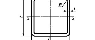
Dimensions
The casing pipe is intended to improve the quality of well operation. If you try to save money on purchasing pipes, then not only the well itself, but also the equipment in it will quickly fall into disrepair. Many people believe that to improve the quality of a well, it is better to choose casing pipes of a larger diameter.
However, the larger the casing size, the higher the flow rate of the water source. To choose the correct diameter of the casing pipe, you need to take into account the consumption of resources. The standard water consumption per hour is 0.7 cubic meters. It is believed that this volume is sufficient for domestic and economic needs. Another important parameter for determining the pipe diameter is the pump performance.
For example, the maximum flow rate is 4 cubic meters per unit of time. For this value, equipment with a diameter of up to 8 cm is recommended. To this parameter is added the possible distance of the pump to the walls of the casing, for example, 5 mm. Next, you can determine the internal diameter of the pipes: D (internal) = D pump + 5 mm; D (internal) – D internal casing pipe; D (pump) – diameter of pumping equipment.
For example, if the pump size is 90 mm, then the value of the internal parameter will be: 90 + 5 = 95. With a pipe wall thickness of 5 mm, the calculated value of the pipe will be: 95 + 5 x 2 = 105 mm. Standard sizes of casing elements: 89, 108, 114, 125 mm, 133 mm. For the example given, it is enough to select a pipe with a diameter of 108 mm.
The given example is simplified; experts also recommend taking into account the depth of laying the casing elements. The casing will have to be lowered until the well reaches the aquifer. When this horizon appears, drilling stops and the upper end of the casing is secured. Pipes are produced in lengths from 9.5 to 13 m with normal and extended threads. The differences between species? Which option is most suitable for a water well?
Assortment
| Options | Values | ||||||
| Pipe diameter, mm | 100 | 160 | 190 | 235 | 285 | 320 | 450 |
| Outer diameter (nipple), mm | 136 | 203 | 240 | 288 | 342 | 378 | 510 |
| Outer diameter (socket), mm | 165 | 240 | 280 | 340 | 400 | 440 | 580 |
| Weight 1 l.m. pipes no more than, kg | 7,2 | 13,3 | 16,5 | 24,1 | 31,0 | 40,5 | 59,0 |
| Bending radius, not less, m | 30 | 40 | 50 | 60 | 70 | 80 | 110 |
Features of using PVC-U casing:
- Pipes are stored and transported on a flat surface, without sharp protrusions or irregularities
- Store in closed or other areas with natural ventilation or under cover. Outdoor storage is allowed for up to 6 months
- Stack to a height of no more than 3 m.
- It is necessary to ensure the safety of pipes from impacts, mechanical damage, and blockages of internal surfaces
- To prevent “foreign” groundwater from entering the well, use rubber gaskets
- Reusing pipes classified as “drinking” that have been used is a violation of the requirements of sanitary legislation and the conditions of state registration of products.
- The threaded connection of the casing pipes is designed for a pressure of 1.0 MPa at 20°C
- Screwing up pipes should be done with special care using special devices to prevent mechanical damage to the pipe.
- Maximum permissible casing installation depth
| Pipe diameter | Wall thickness | Max installation depth, m | Wall type |
| 90 | 5,0 | 185 | reinforced |
| 8,0 | 300 | reinforced | |
| 113 | 5,0 | 90 | standard |
| 7,0 | 260 | reinforced | |
| 10,0 | 300 | reinforced | |
| 125 | 5,0 | 65 | standard |
| 6,0 | 115 | reinforced | |
| 7,5 | 235 | reinforced | |
| 140 | 6,5 | 105 | standard |
| 8,0 | 200 | reinforced | |
| 10,0 | 250 | reinforced | |
| 165 | 7,5 | 100 | standard |
| 9,5 | 205 | reinforced |
- When setting a casing pipe into a well, it is not recommended to drive it (exert mechanical impact). If it is difficult to settle, use pouring water inside the pipe to increase its heaviness.
This is interesting: Aluminum electrodes - types and their features
Reference-list
| Company | Year | Application |
| HALLIBURTON | 2015 | Drillable pipe |
| LUKOIL Western Siberia | 2014 | Infield pipe |
| HALLIBURTON | 2010 | Core pipe |
| LUKOIL Western Siberia | 2005 | Infield pipe |
| Yuganskneftegaz | 2004 | Infield pipe |
| TATNEFT | 1996 | Tubing pipe |
| CHPP No. 27 | 1994 | Pumping table salt |
Tests
Impact with a 100 kg hammer
Pipe bending tests
Joint bending tests
Kinds
All types of casing pipes are structured in a special table of standard requirements. The thickness of the walls, as well as the diameters, must comply with established standards.
Products for wells have a typical accuracy of 0.7 mm per 1 meter of trunk. The diameter of the pipe size can vary from 33.5 to 89 mm. According to the table, this figure is equivalent for pipes 108–146 mm.
PVC pipes for wells are usually blue with a hole diameter of 90–225 mm. For shallow or medium-sized wells, products with wall thicknesses up to 5 mm are suitable. The walls of products for deep wells should be increased - from 5 to 13 mm.
The choice of casing may be related to the method of interconnecting the parts into a single string. The connection methods are as follows:
- welding connection;
- bell joint;
- threaded connection.
Welding is considered a rigid connection between steel segments. This method is rarely used in water well construction. Weak characteristics of the method:
- Labor intensity and the need for a qualified worker.
- The need for special retention systems.
- The holding devices must provide the required clearance.
- The appearance of corrosion in the connecting seam.
- Possibility of inaccurate vertical. A metal pipe connected by welding is more difficult to lower into the well.
Movable connection by element is possible for both PVC and steel structures. The connection occurs by inserting the upper part into the lower one, which must be equipped with a socket. This option is possible for shallow wells. Due to the possible displacement of segments and violation of integrity, this option is also used infrequently.
Threaded casings are the most airtight assembly method. The method, by the way, allows you to install a combined column, which will include both steel segments and PVC parts.
The connection of elements with external threads is carried out using a coupling. If the threads on the casing pipes are present on both the external and internal sides, then the segments can be screwed into each other.
Metal or polymer parts come with internal threads. To connect such elements, nipples are needed. Moreover, if in the first type of connection it is possible to increase the diameter of the penetration, in the second option it is possible to increase the diameter of the hole, in the last type of connection the drilling diameter does not increase.
Documentation
Patent
Patent
ISO9001 Certification
Certificate
Test program
Pipelines for maintaining reservoir pressure RPM
RPM pipes are pipes for maintaining reservoir pressure. In their design and range, they are similar to field pipes, only oil field pipes are designed for pumping out and transporting oil, and water or special solutions are pumped into the oil reservoir using RPM. The RPM system is a complex of technological equipment necessary for the preparation, transportation and injection of the working agent into the reservoir of an oil field in order to maintain reservoir pressure and achieve maximum oil recovery from the reservoir.
The system of equipment for maintaining reservoir pressure (RPM) generally consists of water intake sections, a water supply line (with a large-diameter pipeline and pumping stations of the first, second and, if required, third water lift), treatment facilities for preparing water for injection into the oil reservoir , cluster high-pressure pumping stations in the field area, distribution pipelines with water distribution combs, from which water goes to injection wells.
To maintain reservoir pressure, both natural (fresh or slightly mineralized) and waste (drainage) waters, consisting mainly of reservoir (≈85%), fresh (≈10%) and storm water (≈5%) . Natural and waste waters may contain impurities of organic and inorganic origin. Natural waters may contain various gases, mechanical impurities, iron hydroxide Fe(OH)2 and iron hydroxide Fe(OH)3, as well as microorganisms that, to one degree or another, affect the corrosion process in metal pipes. In addition, droplets of oil may be present in wastewater, as well as a large amount of salts, reaching up to 300 g/l.
Fiberglass pipelines are resistant to transporting aggressive liquids. Pipes are not subject to corrosion (the material of the pipes is inert to acids, salts, alkalis, hydrogen sulfide and oxygen-containing compounds) The small weight of the pipes ensures their high strength (on average, the weight of fiberglass products is 5 times less than the weight of the same metal products).
PPD pipes
Laying PPD pipes
Laying PPD pipes
What is required for certification?
This allows the buyer to include special requirements according to the design and service conditions.
This also allows the product to be manufactured according to the customer's order.
Note that the requirement in the specification must satisfy the need.
Typically, oil and gas utilities create their own FEED specifications, which are front-end engineering and development, or sometimes use available specifications from well-established companies such as Shell, Bechtel, EIL and Chevron.