June 2016. Jeju Island, South Korea. Third day of the international conference on heat pipes. During a break, two Chinese come up:
- Hello! Are you from Terkon? - From Terkon. – Is it true that Yuri Folievich works for you, Maidanik? - Is it true. - So, is he here? - Here. - Is he still alive? So what, can I take a photo with him? - Certainly.
So, several dozen Chinese took photos with our Yuri Folievich that day. First, instead of two, a group of twenty people came. Then they apparently told other Chinese and a couple of smaller groups came to see the living scientist.
This article contains a brief excursion into the history of the appearance of CHPs, how CHPs differ from simple heat pipes, and a series of short videos on how to use CHPs.
History of KTT
Yuri Folievich stood at the origin of the appearance of loop heat pipes (CHPs), invented in what was then Sverdlovsk in the early 1970s. For more than a quarter of a century, CHPs have been successfully used in the space industry. More than 500 CHPs have been launched and are successfully operated on board spacecraft in Russia, the USA, China, and Europe.
In the mid-2000s, the idea of using CTT somewhere not in space, but closer, appeared. In civilian products. To do this, it was necessary to solve two issues - to reduce the size of the CHP and to establish mass production. Space CTTs were large (a tube as thick as a human arm is a common occurrence) and were manufactured individually, individually, for each specific spacecraft. This is how the Terkon-KTT enterprise appeared.
Current model
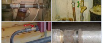
Is it possible to make a heat pipe for the heating system of a private house with your own hands?
Of course, the instructions are not particularly complicated:
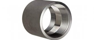
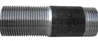
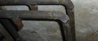
- We weld a glass from the same pipe, oriented perpendicular to its axis, into a steel pipe 2–4 meters long and 100–150 mm in diameter;
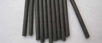
- We place the electrode in the glass, isolating it from the walls;
- Pour a small amount of water into a glass (0.5 - 1 liter);
- We jam the ends of the pipe;
- We fix it with a slight tilt towards the glass;
- We supply phase to the electrode, and zero to the pipe body.
What is the result?
Water, which is an electrolyte due to the salts dissolved in it, boils when current flows through it. The steam condenses at the cold end of the pipe and flows to the glass by gravity. Complete evaporation of water breaks the circuit between the electrode and the wall, after which heating stops.
The author of this design has built into it additional insurance - an electric contact pressure gauge that turns off the power when the pressure rises to 6 atmospheres and turns it on when it drops to 3 kgf/cm. An additional effect was an increase in the operating temperature of the heater: with increased pressure, water boils at a temperature of more than 100 degrees.
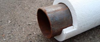
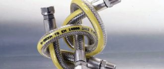
The experiment can be simplified by heating at one end a corrugated stainless steel tube with a small amount of water inside, sealed on both sides. Its second end will instantly become hot.
Heat pipes
Conventional heat pipes (HPs) are a familiar technology today. They are used in almost every modern computer. Be it a desktop PC or a laptop. Heat pipes are used to transfer heat from a source to a heat sink. When it is impossible or not convenient to place the radiator directly on the heat source.
CTs were invented twice (!) in the USA. First by Gogler at General Motors Corporation. Then by Dr. Grover at Los Alamos National Laboratory. The essence of the internal devices of the TT and the principle of its operation:
That is, a TT is a section of pipe with a complex internal structure. When heating occurs on one side of the pipe, the heat passes through the central channel in the form of steam to the other end of the pipe. Then, through the complex capillary structure of the inner walls of the pipe, the cooling liquid returns back. The cycle repeats.
Each CT can transfer a limited amount of heat. In order to transfer more heat, several parallel CTs are used.
Limitations of TT use:
- Small heat transfer distance. In conditions of earth's gravity, when placed vertically, the TT works effectively with a length of up to 25 cm.
- Power. If you need to transfer a lot of heat, it is not always possible to use as many parallel pipes as necessary.
- Configuration. Each bend of the TT significantly affects its efficiency. The complex internal structure of the tube is destroyed when bent. Accordingly, if several sharp bends are required, the use of a CT may become impractical due to a large loss of efficiency.
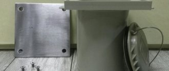
Assembly. First tests and work on the hull
There is already a preliminary result - the CHP has been installed, the computer has been assembled for the first tests (the heat sink is pressed using the backplate)!
Let's check the passive use case - no coolers! Under low load (idle work, surfing, office utilities...) the processor temperature reaches 50 degrees (20 minutes after turning on and watching a movie). You can live, but if you increase the load... Here is a temperature graph when running the built-in CPU-Z stress test:
This is what the thermal imager sees after warming up:
Obviously, a completely passive operating mode is not our case. It is necessary to create at least a small air flow (after all, it took a lot of time to reach the maximum temperatures at maximum load). The fact that a small flow is enough for such a radiator was verified by a 50mm cooler from an ancient video card. Simply throwing it on top of the radiator under the same conditions and testing time, the maximum temperature only reached 87 degrees!
This means that the problem of overheating can be solved with the help of larger coolers (or even several) operating at minimum speeds. But what about their placement? Here we are getting very close to the building.
Loop heat pipes
CHP is a closed system. This is not a piece of pipe.
The CHP consists of an evaporator and a steam line. All the complex filling is in the evaporator. The steam line is an ordinary pipe. When the steam line is bent, there is no significant drop in heat transfer efficiency.
Typically a hard-worked stainless steel pipe is used. A special pipe bender is used to bend the contour to prevent the pipe from breaking. It is also possible to use unhardened stainless steel or copper pipes. This contour can be easily bent by hand, and the risk of pipe fracture is minimal. Even such a curved CHP remains fully operational:
The evaporator is mounted to a heat source. The middle section of the steam line is mounted as a snake inside the radiator to increase the contact area.
Application of CTT
A typical scenario for the appearance of CHP cooling in a customer’s device:
- The customer decides that conventional cooling systems do not allow his device to operate at the required level of efficiency. Either the design of the device does not allow one to effectively solve the heat transfer problem.
- Our specialists clarify with the customer all the essential conditions for the functioning of his device.
- If this is acceptable and can bring tangible benefits, we recommend that the customer make changes to the design of the device. For more efficient operation of the cooling system.
- A cooling system based on the CHP is being designed. The spatial configuration of the cooling circuit is modeled. The type of evaporator is selected.
- Based on the developed documentation, a prototype of the cooling system is manufactured.
- After successful experiments with a prototype, a series of CTTs are manufactured for a specific customer device.
Vacuum radiators: a cynical view of a plumber
First meeting
The key difference between a vacuum radiator and a conventional battery is that water circulates in it only through the lower collector. Along the entire height, the sections are heated precisely thanks to the effect of the notorious heat pipe: when the sealed sections are heated, a certain “lithium bromide liquid” evaporates and transfers heat. Its boiling point is 35 degrees.
Meet: a battery that uses evaporation and condensation of a coolant to transfer heat.
The price of vacuum radiators is significantly higher than that of aluminum and even many bimetallic analogues. Thus, an 8-section battery of domestic production will cost the buyer approximately 6,000 rubles.
Debriefing
Now let's take a look at the key statements of the sellers and try to correlate them with our own common sense:
- Thanks to the small internal volume, the volume of coolant in the heating system is reduced.
Water fills only the lower collector.
The volume of coolant has at least some significance if the heating system is filled with antifreeze, which you have to buy. In all other cases, this parameter only affects the inertia of temperature changes. When using solid fuel boilers, low inertia is completely harmful: with rare heating of the boiler, the batteries must remain warm as long as possible .
A special case is heat accumulators installed in the circuit. They are useful in the case of solid fuel boilers or an electric boiler in combination with a night electricity tariff. With a volume of a thermally insulated tank of at least a cubic meter, the difference between radiators with a volume of 8 liters and 0.5 liters is essentially invisible.
Against the background of the size of the heat accumulator, the difference between sections with different internal volumes is smoothed out.
- The radiator is universal and suitable for both a stand-alone system and a central heating system. If the lower collector, in contact with water in the circuit, is made of stainless steel of sufficient thickness, this argument really speaks in favor of a vacuum radiator. It will actually be able to withstand water hammer or temperature surges, which are not uncommon in central heating systems, without harm. Another thing is that this property is not exclusive: any bimetallic radiator has the same properties.
- There is no need to bleed air. Indeed, air will not accumulate in the radiators themselves: water fills only the lower collector. What does not cancel the formation of an air lock when starting a reset circuit: the bottling is never laid strictly horizontally, at the same level as the boiler outlet and inlet.
The radiator is located above the fill and will be air-filled when the system is reset.
- The service life is at least 50 years.
In an autonomous system, any radiator will last no less. Simply because there are completely no destructive factors:
- The coolant is not enriched with oxygen, which means no corrosion of black steel;
- Water hammers are completely excluded with minimal sanity of the owner;
- Temperature changes are insignificant, which guarantees a long service life of the intersection gaskets;
- Silt and rust are absent as a class, since the water in the circuit is practically not renewed. All debris remains on the coarse filter during the first hours of system operation after startup.
In a central heating system, a vacuum radiator is again in no way superior to a bimetallic radiator, which is designed specifically for extreme operating conditions.
Bimetallic batteries are at least as strong as vacuum batteries.
- The design of the vacuum battery eliminates blockages.
This is true. Water circulates only through the lower collector - a straight pipe without bends or passages with a low speed of coolant movement, where the sludge will settle. Another thing is that (see above) in an autonomous system this quality is not in demand due to the absence of silt.
Connecting a conventional radiator in a bottom-down manner also allows you to completely forget about flushing.
With this connection scheme, the device does not silt up.
- The vacuum radiator has low hydraulic resistance. Another case where advertising doesn't lie. However, an increase in hydraulic resistance in an autonomous system will cause only a slight increase in the load on the circulation pump, and in a central heating system the apartment owner is completely indifferent to this parameter.
It is unlikely that the apartment owner is interested in the hydraulic characteristics of the batteries.
- The device has high heat dissipation. The argument is purely demagogic. In the passport for any vacuum radiator, the manufacturer indicates the thermal power of the section (I dare say, for ideal conditions - for a temperature delta between the coolant and the room air of 70 degrees). So, under ideal conditions, the thermal power is 150 - 170 watts per section. For a typical aluminum radiator, this parameter is 190 - 210 watts. In addition, there is no reason for the device to have unusually high power. The amount of heat that it can take away from the coolant is limited by the area of the walls of the lower collector and their thermal conductivity.
To obtain sufficient power you will need a multi-section accordion.
- The efficiency of the heating device reaches 98%. I don’t understand at all how you can talk about the efficiency of a heating device in isolation from the other components of the system. The heat that remains in the battery will in any case be dissipated in the air of the heated room. Unused thermal energy is transferred by the coolant to the next device in the circuit. The efficiency of the system as a whole is influenced by the quality of thermal insulation of the circuit sections passing through the basement and street and the efficiency of the boiler.
- We allow a temperature range from -20 to +90 C. The temperature range below is limited solely by the type of coolant. If the circuit is filled with antifreeze, which remains liquid at -20C, any radiator will not burst with ice.
If water freezes in the battery, the result will be very predictable.
At +90 C, any heating battery will function, regardless of its material and design.
- Water does not circulate throughout the entire volume of the radiator.
But what difference does it make to the owner how it circulates?
- Using the device eliminates the influence of electromagnetic fields and convection processes on humans (I'm not kidding, this point is actually present in advertising!). Convection (mixing of media under the influence of differences in density during heating) is always present in any unevenly heated environment. The air in the room above the battery is mixed precisely due to this process. In any case, convection does not harm anyone or anything.
Thermal convection ensures that the air in the room is heated throughout the entire volume.
How, in principle, electromagnetic fields can be present in a heating device without its own inductor is also unknown to me. I will also leave the statement that they are harmful or dangerous to the conscience of the authors of the advertisement.
- Vacuum radiators are economical. They allow you to reduce fuel or electricity consumption by 40 - 100% compared to conventional devices. I deliberately left this point for dessert.
The amount of thermal energy required to maintain a constant temperature in the house is determined by:
- Quality of insulation of enclosing structures;
Insulation is the best way to reduce heating costs.
- Temperature delta with the street.
For obvious reasons, the financial costs of heating are affected by the type of heat source used (for example, mains gas will cost much less than diesel fuel) and the efficiency of the boiler.
The design of heating devices does not affect costs. At all. No way, never.
Whatever radiator you choose, fuel costs will not decrease.
Some savings can be achieved by redistributing heat sources. For example, heated floors are somewhat more economical than convection heating because in this case the temperatures in the room are distributed more rationally: there is no overheating of the air under the ceiling, which only leads to an increase in heat loss through the roof.
Temperature distribution during convection heating and above a heated floor.
However, this is clearly not our case. Vacuum batteries, like any other, heat the air through convection. The conclusion is obvious: in this case, advertising shamelessly lies.
Heat pipe batteries are an ordinary heating device, no worse or better than any other. Its current market value is greatly inflated, and the advertising is full of... let's say politely - speculation divorced from reality.
Application of CTT. DIY script
The typical scenario described above is typical for relatively large customers. Modeling and prototypes can cost quite a bit of money. But there is a second way.
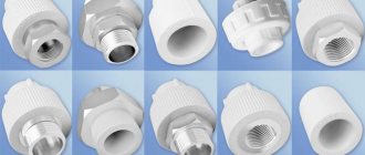
In addition to custom developments, our company’s product range includes so-called “standard CHPs”. This is a set of loop heat pipes of several standard configurations. They are usually in stock and relatively inexpensively can be purchased individually for your experiments.
Understanding the rules of working with CHP, it is quite possible, based on such standard pipes, to make your own cooling system for your small-scale (or even one-piece) product.
You can view the standard CHP options available for purchase on our website. And you can understand the basic rules of working with them by watching our mini-series in the final part of this article.
How it all began
One fine morning I realized that it was time to replace my old (also in a homemade case) PC with something much fresher and more productive. Together with the body, it has become noisy, and there is no reserve for cooling the CO. My firstborn
In terms of choosing components, everything is now quite simple - you don’t even have to think about video cards and forget that such a thing exists (thanks to prices for that).
And the Chinese also offer very affordable and interesting options for mobile CPUs soldered onto a fiberglass substrate for a desktop socket. In total, this is the set: - CPU QNCT - MB Asus H110T Thin Mini ITX - RAM 8Gb DDR4 x2 - SSD 500GB, M.2 2280, SATA III I ’ll add a couple of comments. By processor
— in order to once and for all resolve the issue of the socket COs fitting to the tiny crystal, a heat distribution cover from some ancient processor was added. The cover is ground at the base so that it fits in height to the crystal and on the sides so that it fits onto the substrate:
A little thermal paste and automotive neutral sealant:
SSD
It was originally taken for other purposes, but in the end it was decided to use it in this assembly. And since the motherboard does not structurally support the placement of drives with a length of 80mm or more, I had to use the following adapter: