How to determine gas consumption: methods of measuring and calculating the fuel used
One way or another, you have faced the issue of saving and power of household appliances. Whether at the stage of the first repair or when replacing outdated equipment. It can be useful to calculate gas consumption or the need for it before purchasing a stove or boiler, choosing a gas meter, or its possible replacement. If you have questions about gas charges, if the search for new equipment is a matter of the next few weeks, an accurate method for determining gas consumption and formulas for calculation will make your life easier.
Gas prices are gradually rising, and appliances are becoming more powerful, so it doesn’t hurt to come up with your own strategy to optimize costs. Our article will help you with this. You cannot find out about the current level of gas consumption in your home from conversations with your neighbors; you need accurate information.
Calculation of gas pipeline capacity
Designing a gas pipeline requires fairly high precision - gas has a very high compression ratio, due to which leaks are possible even through microcracks, not to mention serious ruptures. That is why correct calculation of the capacity of the pipe through which gas will be transported is very important.
If we are talking about gas transportation, then the throughput of pipelines, depending on the diameter, will be calculated using the following formula:
- Qmax = 0.67 DN2 * p,
Where p is the value of the working pressure in the pipeline, to which 0.10 MPa is added;
DN – the value of the nominal diameter of the pipe.
The above formula for calculating the capacity of a pipe by diameter allows you to create a system that will work in domestic conditions.
In industrial construction and when performing professional calculations, a different formula is used:
- Qmax = 196.386 DN2 * p/z*T,
Where z is the compression ratio of the transported medium;
T – temperature of the transported gas (K).
This formula allows you to determine the degree of heating of the transported substance depending on the pressure. An increase in temperature leads to expansion of the gas, as a result of which the pressure on the pipe walls increases (read: “Why does pressure loss occur in a pipeline and how can it be avoided”).
To avoid problems, professionals also have to take into account the climatic conditions in the region where it will pass when calculating the pipeline. If the outer diameter of the pipe is smaller than the gas pressure in the system, then the pipeline is very likely to be damaged during operation, resulting in loss of the transported substance and an increased risk of explosion in the weakened section of the pipe.
If necessary, you can determine the permeability of a gas pipe using a table that describes the relationship between the most common pipe diameters and the operating pressure level in them. By and large, the tables have the same drawback that the pipeline capacity calculated by diameter has, namely, the inability to take into account the influence of external factors.
Calculation of liquefied gas consumption
Calculating gas using propane or butane has its own characteristics, but is not particularly difficult. What matters is the density of the flammable substance, which changes with increasing or decreasing temperature and depends on the composition of the gas mixture. Only the weight of the liquefied fuel remains constant.
The volume of gas used differs in winter and summer, so it makes no sense to use m³ units to determine the consumption of liquefied gas per 1 kW of heat; kilograms are taken for designation, which do not change with the change of seasons.
Calculation for 1 kW of heat
The amount is calculated for heating the house and heating the water in the system. If you cook food using gas, this needs to be taken into account additionally.
The formula used is Q = (169.95 / 12.88) F, where:
- Q—fuel mass;
- 169.95 - annual amount of kW for heating 1 m² of a house;
- 12.88 - calorific value of propane;
- F is the quadrature of the structure.
The resulting value is multiplied by the cost of 1 kg of liquefied mixture to calculate the cost of purchasing the required quantity. The price is usually given per 1 kg and not per 1 m³, which should be taken into account.
How to determine gas consumption: methods of measuring and calculating the fuel used
One way or another, you have faced the issue of saving and power of household appliances. Whether at the stage of the first repair or when replacing outdated equipment. It can be useful to calculate gas consumption or the need for it before purchasing a stove or boiler, choosing a gas meter, or its possible replacement. If you have questions about gas charges, if the search for new equipment is a matter of the next few weeks, an accurate method for determining gas consumption and formulas for calculation will make your life easier.
Gas prices are gradually rising, and appliances are becoming more powerful, so it doesn’t hurt to come up with your own strategy to optimize costs. Our article will help you with this. You cannot find out about the current level of gas consumption in your home from conversations with your neighbors; you need accurate information.
Methods and rules for calculating gas consumption by meter
Calculation of gas consumed per month is made based on current and previous readings. To do this, the testimony for the previous month is subtracted from the present testimony. The difference is multiplied by the current tariff. The resulting figure will be the amount that needs to be paid for the service provided. For example, last month 589 cubic meters were consumed, and this month - 630. It turns out 630-589 ⹀ 41 - the volume of gas consumed. Now 41 is multiplied by the cost of gas per 1 cubic meter. m.
Calculation of gas consumption by meter
Many websites of gas companies have online calculators with which you can quickly calculate gas consumption by the meter and the amount to be paid. To do this, follow a few simple steps.
- Indicate the presence or absence of a counter.
- Enter current and previous readings.
- Indicate the number of people living in the house and the presence of beneficiaries.
- After clicking on the “Calculate” button, the required numbers will be displayed on the screen.
Thus, you can find out the payment amount and deposit it into the gas company’s account in any convenient way, the main thing is to do it in a timely manner.
Calculation method for natural gas
The approximate gas consumption for heating is calculated based on half the power of the installed boiler. The thing is that when determining the power of a gas boiler, the lowest temperature is set. This is understandable - even when it is very cold outside, the house should be warm.
You can calculate gas consumption for heating yourself
But calculating gas consumption for heating using this maximum figure is completely incorrect - after all, the temperature is generally much higher, which means much less fuel is burned. That’s why it is generally accepted that the average fuel consumption for heating is about 50% of the heat loss or boiler power.
We calculate gas consumption by heat loss
If you don’t have a boiler yet, and you estimate the cost of heating in different ways, you can calculate it from the total heat loss of the building. They are most likely known to you. The technique here is this: they take 50% of the total heat loss, add 10% to provide hot water supply and 10% to remove heat during ventilation. As a result, we obtain the average consumption in kilowatts per hour.
Next, you can find out the fuel consumption per day (multiply by 24 hours), per month (by 30 days), and, if desired, for the entire heating season (multiply by the number of months during which the heating operates). All these figures can be converted into cubic meters (knowing the specific heat of combustion of gas), and then multiply the cubic meters by the price of gas and, thus, find out the heating costs.
| Crowd name | Unit | Specific heat of combustion in kcal | Specific heat of combustion in kW | Specific heat of combustion in MJ |
| Natural gas | 1 m 3 | 8000 kcal | 9.2 kW | 33.5 MJ |
| Liquefied gas | 1 kg | 10800 kcal | 12.5 kW | 45.2 MJ |
| Coal (W=10%) | 1 kg | 6450 kcal | 7.5 kW | 27 MJ |
| Wood pellets | 1 kg | 4100 kcal | 4.7 kW | 17.17 MJ |
| Dried wood (W=20%) | 1 kg | 3400 kcal | 3.9 kW | 14.24 MJ |
Example of heat loss calculation
Let the heat loss of the house be 16 kW/hour. Let's start counting:
- average heat demand per hour - 8 kW/h + 1.6 kW/h + 1.6 kW/h = 11.2 kW/h;
- per day - 11.2 kW * 24 hours = 268.8 kW;
- per month - 268.8 kW * 30 days = 8064 kW.
Convert to cubic meters. If we use natural gas, we divide the gas consumption for heating per hour: 11.2 kW/h / 9.3 kW = 1.2 m3/h. In calculations, the figure 9.3 kW is the specific heat capacity of natural gas combustion (available in the table).
Since the boiler has not 100% efficiency, but 88-92%, you will have to make further adjustments for this - add about 10% of the obtained figure. In total, we get gas consumption for heating per hour - 1.32 cubic meters per hour. Next you can calculate:
- consumption per day: 1.32 m3 * 24 hours = 28.8 m3/day
- monthly demand: 28.8 m3/day * 30 days = 864 m3/month.
The average consumption for the heating season depends on its duration - multiply by the number of months while the heating season lasts.
This calculation is approximate. In some months, gas consumption will be much less, in the coldest month - more, but on average the figure will be about the same.
Boiler power calculation
The calculations will be a little simpler if you have the calculated boiler power - all the necessary reserves (for hot water supply and ventilation) have already been taken into account. Therefore, we simply take 50% of the calculated capacity and then calculate the consumption per day, month, per season.
For example, the design power of the boiler is 24 kW. To calculate gas consumption for heating, we take half: 12 k/W. This will be the average heat demand per hour. To determine fuel consumption per hour, we divide by the calorific value, we get 12 kW/hour / 9.3 k/W = 1.3 m3. Then everything is calculated as in the example above:
- per day: 12 kW/h * 24 hours = 288 kW in terms of the amount of gas - 1.3 m3 * 24 = 31.2 m3
- per month: 288 kW * 30 days = 8640 m3, consumption in cubic meters 31.2 m3 * 30 = 936 m3.
Next, add 10% for the imperfection of the boiler, we find that for this case the consumption will be slightly more than 1000 cubic meters per month (1029.3 cubic meters). As you can see, in this case everything is even simpler - fewer numbers, but the principle is the same.
By quadrature
Even more approximate calculations can be obtained based on the square footage of the house. There are two ways:
- You can calculate according to SNiP standards - on average, heating one square meter in Central Russia requires 80 W/m2. This figure can be used if your house is built according to all requirements and has good insulation.
- You can estimate based on average statistical data: with good insulation of the house, 2.5-3 cubic meters/m2 is required;
- with average insulation, gas consumption is 4-5 cubic meters/m2.
Each owner can assess the degree of insulation of his home; accordingly, one can estimate what gas consumption will be in this case. For example, for a house of 100 sq. m. with average insulation, 400-500 cubic meters of gas will be required for heating, for a house of 150 square meters it will take 600-750 cubic meters per month, for heating a house with an area of 200 m2 - 800-100 cubic meters of blue fuel. All this is very approximate, but the figures are derived based on many factual data.
Calculation of sewer pipe capacity
When designing a sewer system, it is imperative to calculate the throughput of the pipeline, which directly depends on its type (sewage systems are either pressure or non-pressure). Hydraulic laws are used to carry out calculations. The calculations themselves can be carried out either using formulas or using appropriate tables.
For the hydraulic calculation of the sewer system, the following indicators are required:
- Pipe diameter – DN;
- The average speed of movement of substances is v;
- The magnitude of the hydraulic slope is I;
- Filling degree – h/DN.
As a rule, when carrying out calculations, only the last two parameters are calculated - the rest can then be determined without any problems. The magnitude of the hydraulic slope is usually equal to the slope of the ground, which will ensure the movement of wastewater at the speed necessary for self-cleaning of the system.
The speed and maximum level of filling of domestic sewerage are determined from a table that can be written out as follows:
- 150-250 mm - h/DN is 0.6, and speed is 0.7 m/s.
- Diameter 300-400 mm - h/DN is 0.7, speed - 0.8 m/s.
- Diameter 450-500 mm - h/DN is 0.75, speed - 0.9 m/s.
- Diameter 600-800 mm - h/DN is 0.75, speed - 1 m/s.
- Diameter 900+ mm - h/DN is 0.8, speed - 1.15 m/s.
For a product with a small cross-section, there are standard indicators for the minimum pipeline slope:
- With a diameter of 150 mm, the slope should not be less than 0.008 mm;
- With a diameter of 200 mm, the slope should not be less than 0.007 mm.
To calculate the volume of wastewater, the following formula is used:
- q = a*v,
Where a is the open cross-sectional area of the flow;
v – speed of wastewater transportation.
The speed of transport of a substance can be determined using the following formula:
- v= C√R*i,
where R is the value of the hydraulic radius,
C – wetting coefficient;
i is the degree of slope of the structure.
From the previous formula we can derive the following, which will allow us to determine the value of the hydraulic slope:
- i=v2/C2*R.
To calculate the wetting coefficient, a formula of the following form is used:
- С=(1/n)*R1/6,
Where n is a coefficient that takes into account the degree of roughness, which varies from 0.012 to 0.015 (depending on the material of the pipe).
The R value is usually equated to the usual radius, but this is only relevant if the pipe is completely filled.
For other situations, a simple formula is used:
- R=A/P,
Where A is the cross-sectional area of the water flow,
P is the length of the inner part of the pipe in direct contact with the liquid.
How to determine gas consumption: methods of measuring and calculating the fuel used
One way or another, you have faced the issue of saving and power of household appliances. Whether at the stage of the first repair or when replacing outdated equipment. It can be useful to calculate gas consumption or the need for it before purchasing a stove or boiler, choosing a gas meter, or its possible replacement. If you have questions about gas charges, if the search for new equipment is a matter of the next few weeks, an accurate method for determining gas consumption and formulas for calculation will make your life easier.
Gas prices are gradually rising, and appliances are becoming more powerful, so it doesn’t hurt to come up with your own strategy to optimize costs. Our article will help you with this. You cannot find out about the current level of gas consumption in your home from conversations with your neighbors; you need accurate information.
Functionality, pros and cons
An ultrasonic meter is a metrological device that measures the flow rate of a gaseous medium with high accuracy. At the same time, it is structurally designed in such a way that it does not create additional resistance to the measured medium.
The meters are designed for use in the oil refining and gas industries, and in everyday life. Used to count gas used in homes, administrative buildings and housing and communal services facilities.
They are equipped with programmable computing units that provide:
- Connection to data channels. This allows you to connect them to automated accounting systems;
- When measuring the amount of blue fuel consumed, the software unit corrects the data depending on the ambient temperature, bringing the values to standard.
The advantages of the device include:
- The absence of mechanical parts ensures high reliability of all meter components;
- High-tech units allow the device to be interfaced with various computer systems for collecting and transmitting data. They have analog and digital interfaces. Supports Mobdus protocols (ASCII, RTU, TCP/IP), UNIFORM, MMS, built-in Web server;
- Possibility of on-site diagnostics. Models are available that allow diagnostics to be carried out remotely;
- The meter has a high degree of reliability;
- The absence of mechanical parts made it possible to increase the turnaround time significantly;
- Resistance to vibration and shock;
- Meters can take into account flow in any direction without readjustment;
- Not sensitive to the presence of moisture in a gas environment;
- They are used not only for measuring gas flow, but also water and liquids with physical characteristics similar to water;
- Mounted on pipes of any diameter;
- No maintenance required.
In addition to their advantages, ultrasonic flowmeters have disadvantages. For example, sensitivity to flow distortions. Cannot be used in networks with acoustic noise. Lack of domestic measurement sensors. All this hinders the spread of devices.
Methods for calculating pipeline capacity
There are several methods for calculating this parameter, each of which is suitable for a particular case. Some symbols important when determining pipe capacity:
Outer diameter is the physical size of the pipe cross-section from one edge of the outer wall to the other. In calculations it is designated as Dn or Dn. This parameter is indicated in the labeling.
Nominal diameter is the approximate value of the diameter of the internal section of the pipe, rounded to the nearest whole number. In calculations it is designated as Du or Du.
Physical methods for calculating pipe capacity
Pipe throughput values are determined using special formulas. For each type of product - for gas, water supply, sewerage - there are different calculation methods.
Tabular calculation methods
There is a table of approximate values created to make it easier to determine the capacity of pipes in apartment wiring.
In most cases, high precision is not required, so the values can be applied without complex calculations. But this table does not take into account the decrease in throughput due to the appearance of sedimentary growths inside the pipe, which is typical for old highways. Table 1. Pipe capacity for liquids, gas, water vapor
| Type of liquid | Speed (m/sec) |
| City water | 0,60-1,50 |
| Water pipeline | 1,50-3,00 |
| Central heating water | 2,00-3,00 |
| Pressure system water in pipeline line | 0,75-1,50 |
| Hydraulic fluid | up to 12m/sec |
| Oil pipeline line | 3,00-7,5 |
| Oil in the pressure system of the pipeline line | 0,75-1,25 |
| Steam in the heating system | 20,0-30,00 |
| Steam central piping system | 30,0-50,0 |
| Steam in a high temperature heating system | 50,0-70,00 |
| Air and gas in the central piping system | 20,0-75,00 |
There is an exact table for calculating capacity, called the Shevelev table, which takes into account the pipe material and many other factors. These tables are rarely used when laying water pipes in an apartment, but in a private house with several non-standard risers they can be useful.
Calculation using programs
Modern plumbing companies have special computer programs at their disposal to calculate pipe capacity, as well as many other similar parameters. In addition, online calculators have been developed, which, although less accurate, are free and do not require installation on a PC. One of the stationary programs “TAScope” is a creation of Western engineers, which is shareware. In large ones, this is a domestic program that calculates pipes according to criteria that affect their operation in the regions of the Russian Federation. In addition to hydraulic calculations, it allows you to calculate other pipeline parameters. The average price is 150,000 rubles.
How to determine gas consumption: methods of measuring and calculating the fuel used
One way or another, you have faced the issue of saving and power of household appliances. Whether at the stage of the first repair or when replacing outdated equipment. It can be useful to calculate gas consumption or the need for it before purchasing a stove or boiler, choosing a gas meter, or its possible replacement. If you have questions about gas charges, if the search for new equipment is a matter of the next few weeks, an accurate method for determining gas consumption and formulas for calculation will make your life easier.
Gas prices are gradually rising, and appliances are becoming more powerful, so it doesn’t hurt to come up with your own strategy to optimize costs. Our article will help you with this. You cannot find out about the current level of gas consumption in your home from conversations with your neighbors; you need accurate information.
Calculation of liquefied gas consumption
Calculating gas using propane or butane has its own characteristics, but is not particularly difficult. What matters is the density of the flammable substance, which changes with increasing or decreasing temperature and depends on the composition of the gas mixture. Only the weight of the liquefied fuel remains constant.
The volume of gas used differs in winter and summer, so it makes no sense to use m³ units to determine the consumption of liquefied gas per 1 kW of heat; kilograms are taken for designation, which do not change with the change of seasons.
Calculation for 1 kW of heat
The amount is calculated for heating the house and heating the water in the system. If you cook food using gas, this needs to be taken into account additionally.
The formula used is Q = (169.95 / 12.88) F, where:
- Q—fuel mass;
- 169.95 - annual amount of kW for heating 1 m² of a house;
- 12.88 - calorific value of propane;
- F is the quadrature of the structure.
The resulting value is multiplied by the cost of 1 kg of liquefied mixture to calculate the cost of purchasing the required quantity. The price is usually given per 1 kg and not per 1 m³, which should be taken into account.
The influence of various factors on the operation of the water supply network
At first glance, the mechanism is simple - there is a line with a certain diameter and the larger it is, the more liquid will pass through it at a certain pressure.
Of course, these are effective factors influencing water consumption and the intensity of its movement through the water supply network. But this is only the beginning of a long list, since besides them there are other influences:
- Pipe length. As the fluid moves, it experiences the opposite direction of flow from friction against the pipe walls. The magnitude of the resistance is such that it cannot be neglected. Of course, on the console through the drain hole the flow rate depends only on the pressure. But the leaked liquid needs to be replaced, and the speed is insufficient due to resistance.
- The diameter of the internal cross-section of the pipeline has a direct effect on the fluid flow rate. The smaller it is, the stronger the flow resistance is, since the contact area in relation to the volume of flowing water increases. That is, there is an inversely proportional relationship between these parameters.
- The material from which the round pipe is made also has a significant impact. The inner surface of plastic products made from cross-linked polyethylene is smoother than those made from metal. It has much less resistance to flow. Moreover, when calculating the fluid velocity in a pipeline made of metal, it should be understood that it is only valid for a new system. Such systems very quickly become clogged with lime deposits on the internal walls and metal oxidation products. It is impossible to take such impacts into account, since the intensity of their accumulation largely depends on the quality of the water. The resistance value in a new pipe and a clogged one can increase up to 200 times.
- The speed of fluid movement in a pipeline system largely depends on its complexity. Every turn, every fitting is a loss of speed, and the degree of influence is not limited to statistical error, but reduces the maneuverability many times over.
Taking into account the above, it is obvious that it is almost impossible to reliably determine the main parameters of the operation of a water supply system using hydraulic calculations. However, calculating the water speed in the pipeline is necessary to determine the primary data on its main characteristics and it must be done using a calculator using the online mode.
How to calculate gas consumption for home heating
Gas is still the cheapest type of fuel, but the cost of connection is sometimes very high, so many people want to first assess how economically justified such expenses are. To do this, you need to know the gas consumption for heating, then you can estimate the total cost and compare it with other types of fuel.
Calculation method for natural gas
The approximate gas consumption for heating is calculated based on half the power of the installed boiler. The thing is that when determining the power of a gas boiler, the lowest temperature is set. This is understandable - even when it is very cold outside, the house should be warm.
You can calculate gas consumption for heating yourself
But calculating gas consumption for heating using this maximum figure is completely incorrect - after all, the temperature is generally much higher, which means much less fuel is burned. That’s why it is generally accepted that the average fuel consumption for heating is about 50% of the heat loss or boiler power.
We calculate gas consumption by heat loss
If you don’t have a boiler yet, and you estimate the cost of heating in different ways, you can calculate it from the total heat loss of the building. They are most likely known to you. The technique here is this: they take 50% of the total heat loss, add 10% to provide hot water supply and 10% to remove heat during ventilation. As a result, we obtain the average consumption in kilowatts per hour.
Next, you can find out the fuel consumption per day (multiply by 24 hours), per month (by 30 days), and, if desired, for the entire heating season (multiply by the number of months during which the heating operates). All these figures can be converted into cubic meters (knowing the specific heat of combustion of gas), and then multiply the cubic meters by the price of gas and, thus, find out the heating costs.
Example of heat loss calculation
Let the heat loss of the house be 16 kW/hour. Let's start counting:
- average heat demand per hour - 8 kW/h + 1.6 kW/h + 1.6 kW/h = 11.2 kW/h;
- per day - 11.2 kW * 24 hours = 268.8 kW;
- per month - 268.8 kW * 30 days = 8064 kW.
The actual gas consumption for heating also depends on the type of burner - modulating ones are the most economical
Convert to cubic meters. If we use natural gas, we divide the gas consumption for heating per hour: 11.2 kW/h / 9.3 kW = 1.2 m3/h. In calculations, the figure 9.3 kW is the specific heat capacity of natural gas combustion (available in the table).
By the way, you can also calculate the required amount of fuel of any type - you just need to take the heat capacity for the required fuel.
Since the boiler has not 100% efficiency, but 88-92%, you will have to make further adjustments for this - add about 10% of the obtained figure. In total, we get gas consumption for heating per hour - 1.32 cubic meters per hour. Next you can calculate:
- consumption per day: 1.32 m3 * 24 hours = 28.8 m3/day
- monthly demand: 28.8 m3/day * 30 days = 864 m3/month.
The average consumption for the heating season depends on its duration - multiply by the number of months while the heating season lasts.
This calculation is approximate. In some months, gas consumption will be much less, in the coldest month - more, but on average the figure will be about the same.
Boiler power calculation
The calculations will be a little simpler if you have the calculated boiler power - all the necessary reserves (for hot water supply and ventilation) have already been taken into account. Therefore, we simply take 50% of the calculated capacity and then calculate the consumption per day, month, per season.
For example, the design power of the boiler is 24 kW. To calculate gas consumption for heating, we take half: 12 k/W. This will be the average heat demand per hour. To determine fuel consumption per hour, we divide by the calorific value, we get 12 kW/hour / 9.3 k/W = 1.3 m3. Then everything is calculated as in the example above:
- per day: 12 kW/h * 24 hours = 288 kW in terms of the amount of gas - 1.3 m3 * 24 = 31.2 m3
- per month: 288 kW * 30 days = 8640 m3, consumption in cubic meters 31.2 m3 * 30 = 936 m3.
You can calculate gas consumption for heating a house using the design capacity of the boiler
Next, add 10% for the imperfection of the boiler, we find that for this case the consumption will be slightly more than 1000 cubic meters per month (1029.3 cubic meters). As you can see, in this case everything is even simpler - fewer numbers, but the principle is the same.
By quadrature
Even more approximate calculations can be obtained based on the square footage of the house. There are two ways:
Counters
What data is needed for heat accounting?
It's easy to guess:
- The flow rate of coolant passing through heating devices.
- Its temperature at the inlet and outlet of the corresponding section of the circuit.
Two types of meters are used to measure flow.
Meters with impeller
Meters intended for heating and hot water supply differ from those used for cold water only in the material of the impeller: it is more resistant to high temperatures.
The mechanism itself is the same:
- The coolant flow causes the impeller to rotate.
- It transmits rotation to the metering mechanism without direct interaction, through a permanent magnet.
Despite the simplicity of the design, the meters have a fairly low response threshold and are well protected from data tampering: any attempt to slow down the impeller with an external magnetic field will be hindered by the presence of an antimagnetic screen in the mechanism.
Meters with differential recorder
The device of the second type of meters is based on Bernoulli's law, which states that the static pressure in a flow of liquid or gas is inversely proportional to its speed.
How to use this feature of hydrodynamics to calculate coolant flow? It is enough to block his path with a retaining washer. The pressure drop across the washer will be directly proportional to the flow rate through it. By recording pressure with a pair of sensors, it is easy to calculate flow in real time.
But what if we are not talking about a closed heating circuit, but about an open system with the possibility of selecting hot water? How to record hot water consumption?
The solution is obvious: in this case, retaining washers and pressure sensors are placed on both the feeder and the . The difference in coolant flow between the threads will indicate the amount of hot water that was used for household needs.
The photo shows an electronic heat meter with pressure drop recording on the washers.
Water pipe capacity
Water pipes are the most commonly used pipes in a home. And since they are subject to a large load, calculating the throughput of the water main becomes an important condition for reliable operation.
Pipe patency depending on diameter
Diameter is not the most important parameter when calculating the patency of a pipe, but it also affects its value. The larger the internal diameter of the pipe, the higher the permeability, and also the lower the chance of blockages and plugs. However, in addition to the diameter, it is necessary to take into account the coefficient of friction of water on the pipe walls (tabular value for each material), the length of the line and the difference in liquid pressure at the inlet and outlet. In addition, the number of elbows and fittings in the pipeline will greatly influence the flow rate.
Table of pipe capacity by coolant temperature
The higher the temperature in the pipe, the lower its throughput, since the water expands and thereby creates additional friction. For plumbing this is not important, but in heating systems it is a key parameter.
There is a table for calculations of heat and coolant.
Table 5. Pipe throughput depending on the coolant and heat output
| Pipe diameter, mm | Bandwidth | |||
| By warmth | By coolant | |||
| Water | Steam | Water | Steam | |
| Gcal/h | t/h | |||
| 15 | 0,011 | 0,005 | 0,182 | 0,009 |
| 25 | 0,039 | 0,018 | 0,650 | 0,033 |
| 38 | 0,11 | 0,05 | 1,82 | 0,091 |
| 50 | 0,24 | 0,11 | 4,00 | 0,20 |
| 75 | 0,72 | 0,33 | 12,0 | 0,60 |
| 100 | 1,51 | 0,69 | 25,0 | 1,25 |
| 125 | 2,70 | 1,24 | 45,0 | 2,25 |
| 150 | 4,36 | 2,00 | 72,8 | 3,64 |
| 200 | 9,23 | 4,24 | 154 | 7,70 |
| 250 | 16,6 | 7,60 | 276 | 13,8 |
| 300 | 26,6 | 12,2 | 444 | 22,2 |
| 350 | 40,3 | 18,5 | 672 | 33,6 |
| 400 | 56,5 | 26,0 | 940 | 47,0 |
| 450 | 68,3 | 36,0 | 1310 | 65,5 |
| 500 | 103 | 47,4 | 1730 | 86,5 |
| 600 | 167 | 76,5 | 2780 | 139 |
| 700 | 250 | 115 | 4160 | 208 |
| 800 | 354 | 162 | 5900 | 295 |
| 900 | 633 | 291 | 10500 | 525 |
| 1000 | 1020 | 470 | 17100 | 855 |
Table of pipe capacity depending on coolant pressure
There is a table describing the capacity of pipes depending on pressure.
Table 6. Pipe capacity depending on the pressure of the transported liquid
| Consumption | Bandwidth | ||||||||
| Du pipe | 15 mm | 20 mm | 25 mm | 32 mm | 40 mm | 50 mm | 65 mm | 80 mm | 100 mm |
| Pa/m - mbar/m | less than 0.15 m/s | 0.15 m/s | 0.3 m/s | ||||||
| 90,0 — 0,900 | 173 | 403 | 745 | 1627 | 2488 | 4716 | 9612 | 14940 | 30240 |
| 92,5 — 0,925 | 176 | 407 | 756 | 1652 | 2524 | 4788 | 9756 | 15156 | 30672 |
| 95,0 — 0,950 | 176 | 414 | 767 | 1678 | 2560 | 4860 | 9900 | 15372 | 31104 |
| 97,5 — 0,975 | 180 | 421 | 778 | 1699 | 2596 | 4932 | 10044 | 15552 | 31500 |
| 100,0 — 1,000 | 184 | 425 | 788 | 1724 | 2632 | 5004 | 10152 | 15768 | 31932 |
| 120,0 — 1,200 | 202 | 472 | 871 | 1897 | 2898 | 5508 | 11196 | 17352 | 35100 |
| 140,0 — 1,400 | 220 | 511 | 943 | 2059 | 3143 | 5976 | 12132 | 18792 | 38160 |
| 160,0 — 1,600 | 234 | 547 | 1015 | 2210 | 3373 | 6408 | 12996 | 20160 | 40680 |
| 180,0 — 1,800 | 252 | 583 | 1080 | 2354 | 3589 | 6804 | 13824 | 21420 | 43200 |
| 200,0 — 2,000 | 266 | 619 | 1151 | 2486 | 3780 | 7200 | 14580 | 22644 | 45720 |
| 220,0 — 2,200 | 281 | 652 | 1202 | 2617 | 3996 | 7560 | 15336 | 23760 | 47880 |
| 240,0 — 2,400 | 288 | 680 | 1256 | 2740 | 4176 | 7920 | 16056 | 24876 | 50400 |
| 260,0 — 2,600 | 306 | 713 | 1310 | 2855 | 4356 | 8244 | 16740 | 25920 | 52200 |
| 280,0 — 2,800 | 317 | 742 | 1364 | 2970 | 4356 | 8566 | 17338 | 26928 | 54360 |
| 300,0 — 3,000 | 331 | 767 | 1415 | 3076 | 4680 | 8892 | 18000 | 27900 | 56160 |
Table of pipe capacity depending on diameter (according to Shevelev)
The tables of F.A. and A.F. Shevelev are one of the most accurate tabular methods for calculating the throughput of a water pipeline. In addition, they contain all the necessary calculation formulas for each specific material. This is a lengthy piece of information that is most often used by hydraulic engineers.
The tables take into account:
- pipe diameters – internal and external;
- wall thickness;
- service life of the water supply system;
- line length;
- purpose of pipes.
Hydraulic calculation formula
For water pipes, the following calculation formula is used:
Consumption rates for HBO-4
Experts usually call the figure 10-20% relative to gasoline consumption (in liters). The explanation for this is simple. The first clients of gas workers were taxi drivers, for whom the car was, first of all, a source of income. Therefore, every liter counts, and it’s even better if you managed to save it.
You may be interested >> How to distinguish a car gas cylinder
The vehicle fleet mainly consisted of inexpensive products from the Korean automobile industry, Daewoo small cars of the Nexia and Lanos models, on which it was possible to adjust the gas consumption of the 4th generation LPG to the desired 10%. At the same time, the owners did not have any special requirements for dynamic performance or speed; they were interested in other criteria for engine operation.
Further. Every self-respecting manufacturer of gas-cylinder units, in response to the question about normalized consumption after switching to gas, will give an indicator of 1.2 in relation to driving on regular fuel. Adjusting the ignition timing (installing a variator) will allow you to gain another 5 to 10% - no more.
The gluttony of a four-wheeled horse also depends on the state of the environment; this is pure physics: at low temperatures, gas consumption will always be greater. Ultimately, this parameter falls within the specified 10-20%. This especially needs to be remembered by those who want to preserve the life of the engine and not speed up the overhaul. Incorrect setting, among other things, increases the temperature of the exhaust combustion products by almost 2 times - up to 1400ºС, and all this is due to a lean mixture.
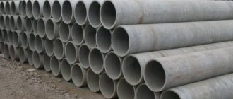
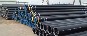
How to calculate the capacity of a gas pipe
Gas is one of the most difficult materials to transport, in particular because it tends to be compressed and therefore is able to leak through the smallest gaps in pipes. There are special requirements for calculating the capacity of gas pipes (as well as for designing the gas system as a whole).
Formula for calculating the capacity of a gas pipe
The maximum throughput of gas pipelines is determined by the formula:
Qmax = 0.67 DN2 * p
where p is equal to the operating pressure in the gas pipeline system + 0.10 MPa or absolute gas pressure;
Du - nominal diameter of the pipe.
There is a complex formula for calculating the capacity of a gas pipe. It is usually not used when carrying out preliminary calculations, as well as when calculating a household gas pipeline.
Qmax = 196.386 DN2 * p/z*T
where z is the compressibility coefficient;
T is the temperature of the transported gas, K;
According to this formula, the direct dependence of the temperature of the moving medium on pressure is determined. The higher the T value, the more the gas expands and presses on the walls. Therefore, when calculating large highways, engineers take into account possible weather conditions in the area where the pipeline runs. If the nominal value of the DN pipe is less than the gas pressure generated at high temperatures in summer (for example, at +38 ... + 45 degrees Celsius), then damage to the line is likely. This entails the leakage of valuable raw materials and creates the possibility of an explosion in a section of the pipe.
Table of gas pipe capacities depending on pressure
There is a table for calculating gas pipeline throughputs for commonly used pipe diameters and nominal operating pressures. To determine the characteristics of a gas pipeline of non-standard sizes and pressures, engineering calculations will be required. The pressure, speed and volume of gas are also affected by the outside air temperature.
The maximum speed (W) of the gas in the table is 25 m/s, and z (compressibility coefficient) is 1. The temperature (T) is 20 degrees Celsius or 293 Kelvin.
Table 2. Gas pipeline capacity depending on pressure
| Work.(MPa) | Pipeline capacity (m?/h), with wgas=25m/s;z=1;T=20?C=293?K | |||||||
| DN 50 | DN 80 | DN 100 | DN 150 | DN 200 | DN 300 | DN 400 | DN 500 | |
| 0,3 | 670 | 1715 | 2680 | 6030 | 10720 | 24120 | 42880 | 67000 |
| 0,6 | 1170 | 3000 | 4690 | 10550 | 18760 | 42210 | 75040 | 117000 |
| 1,2 | 2175 | 5570 | 8710 | 19595 | 34840 | 78390 | 139360 | 217500 |
| 1,6 | 2845 | 7290 | 11390 | 25625 | 45560 | 102510 | 182240 | 284500 |
| 2,5 | 4355 | 11145 | 17420 | 39195 | 69680 | 156780 | 278720 | 435500 |
| 3,5 | 6030 | 15435 | 24120 | 54270 | 96480 | 217080 | 385920 | 603000 |
| 5,5 | 9380 | 24010 | 37520 | 84420 | 150080 | 337680 | 600320 | 938000 |
| 7,5 | 12730 | 32585 | 50920 | 114570 | 203680 | 458280 | 814720 | 1273000 |
| 10,0 | 16915 | 43305 | 67670 | 152255 | 270680 | 609030 | 108720 | 1691500 |
How to take meter readings?
Taking readings from the meter will not cause difficulties. Each counter has a mechanical display with rollers on which numbers are printed. In most cases, there are 7 or 8 videos, of which the 3 on the right are separated by a comma and placed in a red frame. They are not paid attention to when taking readings. For example, if the counter display shows 00458, 356, then the numbers 356 are not taken into account, and the data on the number of cubes consumed will be the numbers 00458. They are entered into the receipt, but without zeros. If one of the clips is stuck between numbers, then the previous one is recorded, for example, 9 is selected from 9 and 0.
Taking readings from the gas meter
The readings are calculated using the same principle if an electronic blue fuel consumption device is installed.
Calculation of the volume and capacity of round and profile pipes
Major home renovations or replacement of plumbing always involve the installation of pipelines. In its design, you cannot do everything “by eye”, otherwise even the most insignificant, at first glance, mistakes often lead to serious consequences. Let's look at what bandwidth is and how to calculate it.
This value reflects the amount of liquid, gas or air that can pass through a pipeline of one size or another in an hour or second.
It allows you to correctly select and install pipes, taking into account the characteristics of water intake points, be it a bathroom, dishwasher, central water supply system, etc.
The service life of the pipes, as well as the normal water pressure after they are started, depend on correctly selected plumbing fixtures.
Bandwidth is calculated using several methods:
- Physical. Depending on the purpose for which the pipeline is intended and what liquids will pass through it, the appropriate formulas are applied. Average indicators are used, for example, roughness coefficient.
- Tabular. There are graphs of approximate values that do not take into account extraneous factors: overgrowth, silt formation.
- Computer programs and online calculators. They are free and are great for calculating the operating parameters of pipes for any purpose.
The last method is the simplest and most accessible for those who want to install a water supply system with their own hands. The calculation is suitable not only for round, but also for square pipes. You don’t have to resort to complex calculations; you just need to enter the data requested by the site. You will receive a result containing the following parameters:
- total area, volume and length of the pipe;
- throughput in kg/hour and kg/sec;
- fluid flow rate in kg/hour and kg/sec.
To obtain this information, you only need to select the type of pipe, enter its diameter, length and wall thickness. You will also need to indicate the flow rate in the pipe.
What does the pipe diameter affect?
This is one of the main characteristics of the pipe system that you should pay attention to during installation. Without it, it will not be possible to determine the throughput and ensure normal fluid supply. Regardless of which material you choose: plastic or metal, the diameter will still play a decisive role.
Calculation of annual operating and capital costs for the industry. boiler room
Dg tech=Dch tech* Ttech
Dg tech
=139(t/hour)*6000(hour)=834000(t/year)
Dh tech
— hourly steam consumption for technological production needs
Ttech
— number of hours of heat load use for technological needs
Dg sn=Dch sn*Tr
Dg sn
=31(t/hour)*6000(hour)=186000(t/year)
Tr
— number of hours of operation of the boiler room
Dh sn
— hourly steam consumption for own needs
Dg sp=( Q h heating -
G sp*Tp*Sr*10 -3)*10 3 /(i p p - i k ) *0.98
Dh sp
=(98(Gcal/hour)-28.8(t/hour)*103(g)*4.19(KJ/kg g)*10^(-3))*10^3/(701(Kcal/kg)-50 (g)*4.19(KJ/kg g)*0.98)=177.7(t/hour)
Dg sp=Dch sp*Tr
Dg sp=177.7(t/hour)*6000(hour)=1066290(t/year)
Q h heating
— heating load of the residential village
G sp
— average hourly consumption of make-up water to replenish the heating network (t/hour)
Tp
— make-up water temperature
Wed
— heat capacity of water (KJ/kg*g)
i p p
— enthalpy of fresh water
i to
— condensate enthalpy
Dg cat=(Dg tech + Dg sn + Dg sp)0.98
Dg cat
=(834000(t/year)+ 186000(t/year)+1066290(t/year))*0.98=2044564(t/year)
Dg tech
— annual steam production for technological needs
Dg sp
— annual steam production for own needs
Dg sp
— annual steam production for network heaters
Q g cat=Dg cat*( i p p -t p c)*10 -3
Q g cat=
2044564(t/year)*( 701(Kcal/kg)-102(g)*4.19(KJ/kg g))*10^-3=559434(GJ/year)
Dg cat
— (t steam/year)
i p p, t p in
— enthalpy of fresh steam and feed water (KJ/kg)
Vgu cat=
Q g cat 29.3*KPDrez*KPDcat
Vgu cat1=
559.4(MJ/year)*10^(3)/29.3(MJ/kg)*0.97*0.84=23431.7(here/year)
Vgu cat2=
559.4(MJ/year)*10^(3)/29.3(MJ/kg)*0.97*0.84=23431.7(here/year)
Vgu cat3=
559.4(MJ/year)*10^(3)/29.3(MJ/kg)*0.97*0.914=21534.6(here/year)
Q g cat
— annual fuel productivity (GJ/year)
29.3
— calorific value of standard fuel (MJ/kg)
KPDcat
— Boiler room efficiency
Efficiency
— coefficient taking into account fuel losses in unsteady mode
Vgn cat=Vgu cat Ke
Vgn cat1=
23431.7(here/year)/0.863=27151(here/year)
Vgn cat2=
23431.7(here/year)/0.749=31284(here/year)
Vgn cat3=
21534.6(here/year)/1.19=18096(here/year)
VGU cat
— standard fuel (here/year)
Ke
— calorie equivalent (here/tnt)
Meters for measuring fuel consumption
The meter measures the amount of gas at different conditions of temperature and pressure and, using special equipment, brings the result to the indicator that will be under standard conditions (SU) - +20 °C and 101 kPa.
The volume of fuel for the control system is determined by the formula Vс = V×(p×Tс/pс×T×K), where
- V is the volume of gas;
- p—density;
- T—thermodynamic temperature;
- K is the fuel compressibility coefficient.
Values with the letter “c” are indicators for standard conditions, without - for workers.
In everyday life, membrane, rotary and ultrasonic meters are used, in large enterprises - turbine and vortex meters - these are the most popular types of gas meters. In gas industry plants, volume is determined mainly by variable pressure changes in constrictions, often between 2 flange connections in close proximity. The meters differ in their operating features.
Diaphragm flowmeters provide minimal calculation errors and consume little electricity. The devices provide readings over a wide range, but with a low maximum pressure - up to 0.5 bar. In everyday life, the meter performs best, since the calibration interval reaches up to 10 years with high reliability of the device. The design does not respond well to mechanical gas contamination and is generally very bulky.
Rotary, or rotary, models do not depend on the electrical network; they are suitable for small industrial facilities, but they are less convenient. With a small installation area and high precision under conditions of sudden pressure changes, they make noise and more often fail. They are “afraid” of pneumatic shocks and pollution.
Ultrasonic meters are small in size and vary significantly in the complexity of their structure. Acoustic gas meters are valued for their reliability and ease of installation. Some devices contain non-volatile memory. Meters for standard sizes G1.6 and G2.5 are relatively expensive.
Turbine devices are used to measure the amount of household and aggressive gases and multicomponent compositions. Meters have become widespread at gas pipelines and chemical plants. Turbine devices record large quantities of gas at pressures up to 10 MPa and vary significantly in size and operating pressure. These are universal instruments for measuring natural gas flow in industry.
Vortex meters measure the volume of natural or inert gases. In terms of measurement range they have an advantage over other models. They detect the slightest movements in the gas mixture and determine large quantities of gas per diameter. The efficiency of a vortex flow meter is directly proportional to the fuel flow rate.
Measurement methods used in gas flow meters
Fuel consumption is calculated using direct and indirect methods.
In the case of direct gas, gas fills the measuring chambers and leaves them. The volume passed correlates with the filling-emptying cycles. Counting in membrane, rotary and drum counters works according to the described principle.
Gas meters with an indirect measurement method work with speed indicators and a known cross-sectional area. The counting method can be mechanical or other, related to the characteristics of the counter. In mechanics, turbines, impellers, and balancing elements are used.
The indirect method of calculation has other methods:
- vortex detection;
- measuring the pressure difference on the constriction device;
- calculation of heat transfer from a heated body;
- measurement of velocity pressure;
- counting based on ultrasonic movement.
The correctness of indirect methods depends on the correspondence of the speed in direction and cross-section. Flow preparation means help: turbulators, condensers and flow straighteners. The devices come separately or as elements of meters.
The devices can determine the difference in speed across the cross section simultaneously with the speed of gas movement and thus reduce the error. The latter often occurs due to fuel stagnation near the walls. Read more about direct and indirect methods for determining gas consumption below.
How is gas pressure determined?
Pressure is measured directly using pressure gauges or by adding the values of atmospheric (Pb) and excess pressure (Pi). Pb is measured at the location of the Pi converter, if the latter is in a closed space and there is pressure or vacuum in it.
The pressure tapping hole for vertical and horizontal pipes is placed radially. On a transverse pipeline it is located in the upper half of the section.
In flow meters without the specified hole, sampling is carried out in front of the meter, at a distance of 1 to 3 pipeline diameters, with a reference point from the gas meter inlet flange.
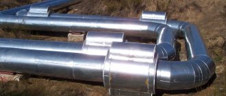
Determination of the capacity of GDS pipelines
B.K. Kovalev, Deputy Director for R&D
Recently, we have increasingly come across examples where orders for industrial gas equipment are placed by managers who do not have sufficient experience and technical knowledge regarding the subject of procurement. Sometimes the result is an incompletely correct application or a fundamentally incorrect selection of the ordered equipment. One of the most common mistakes is the selection of nominal cross-sections of the inlet and outlet pipelines of a gas distribution station, focused only on the nominal values of gas pressure in the pipeline without taking into account the gas flow rate. The purpose of this article is to provide recommendations for determining the capacity of gas distribution station pipelines, allowing, when choosing the standard size of a gas distribution station, to carry out a preliminary assessment of its performance for specific values of operating pressures and nominal diameters of inlet and outlet pipelines.
When choosing the required standard sizes of GDS equipment, one of the main criteria is productivity, which largely depends on the throughput of the inlet and outlet pipelines.
The throughput of the gas distribution station pipelines is calculated taking into account the requirements of regulatory documents that limit the maximum permissible gas flow rate in the pipeline to 25 m/s. In turn, the gas flow rate depends mainly on the gas pressure and the cross-sectional area of the pipeline, as well as on the compressibility of the gas and its temperature.
The throughput capacity of a pipeline can be calculated from the classical formula for the speed of gas movement in a gas pipeline (Handbook for the design of main gas pipelines, edited by A.K. Dertsakyan, 1977):
where W is the speed of gas movement in the gas pipeline, m/sec; Q is the gas flow through a given section (at 20°C and 760 mm Hg), m3/h; z is the compressibility coefficient (for an ideal gas z = 1); T = (273 + t °C) — gas temperature, °K; D is the internal diameter of the pipeline, cm; p = (Pwork + 1.033) — absolute gas pressure, kgf/cm2 (atm); In the SI system (1 kgf/cm2 = 0.098 MPa; 1 mm = 0.1 cm), the specified formula will take the following form:
where D is the internal diameter of the pipeline, mm; p = (Pwork + 0.1012) - absolute gas pressure, MPa. It follows that the pipeline capacity Qmax, corresponding to the maximum gas flow rate w = 25 m/sec, is determined by the formula:
For preliminary calculations, we can take z = 1; T = 20? C = 293? K and carry out calculations with a sufficient degree of reliability using the simplified formula:
The throughput values of pipelines with the most common nominal diameters in gas distribution systems at various gas pressures are given in Table 1.
| Work.(MPa) | Pipeline capacity (m?/h), with wgas=25 m/s; z = 1; T= 20? C = 293? K | |||||||
| DN 50 | DN 80 | DN 100 | DN 150 | DN 200 | DN 300 | DN 400 | DN 500 | |
| 0,3 | 670 | 1715 | 2680 | 6030 | 10720 | 24120 | 42880 | 67000 |
| 0,6 | 1170 | 3000 | 4690 | 10550 | 18760 | 42210 | 75040 | 117000 |
| 1,2 | 2175 | 5570 | 8710 | 19595 | 34840 | 78390 | 139360 | 217500 |
| 1,6 | 2845 | 7290 | 11390 | 25625 | 45560 | 102510 | 182240 | 284500 |
| 2,5 | 4355 | 11145 | 17420 | 39195 | 69680 | 156780 | 278720 | 435500 |
| 3,5 | 6030 | 15435 | 24120 | 54270 | 96480 | 217080 | 385920 | 603000 |
| 5,5 | 9380 | 24010 | 37520 | 84420 | 150080 | 337680 | 600320 | 938000 |
| 7,5 | 12730 | 32585 | 50920 | 114570 | 203680 | 458280 | 814720 | 1273000 |
| 10,0 | 16915 | 43305 | 67670 | 152255 | 270680 | 609030 | 108720 | 1691500 |
Note: for a preliminary assessment of the throughput of pipelines, the internal diameters of the pipes are taken equal to their conventional values (DN 50; 80; 100; 150; 200; 300; 400; 500).
Examples of using the table:
1. Determine the capacity of the gas distribution station with DNin=100mm, DNout=150mm, with PNin=2.5 - 5.5 MPa and PNout=1.2 MPa.
From Table 1 we find that the capacity of the output pipeline DN=150mm at PN=1.2 MPa will be 19595 m3/h, at the same time the input pipeline DN=100mm at PN=5.5 MPa will be able to pass 37520 m3/h, and at PN=2.5 MPa - only 17420 m3/h. Thus, this GDS with PNin = 2.5 - 5.5 MPa and PNout = 1.2 MPa will be able to maximum flow from 17420 to 19595 m3/h. Note: more accurate Qmax values can be obtained from formula (3).
2. Determine the diameter of the GDS outlet pipeline, with a capacity of 5000 m3/h at Pin=3.5 MPa for output pressures Pout1=1.2 MPa and Pout2=0.3 MPa.
From Table 1 we find that a throughput capacity of 5000 m3/hour at Pout=1.2 MPa will be provided by a pipeline DN=80mm, and at Pout=0.3 MPa - only DN=150mm. In this case, it is enough to have a pipeline DN=50mm at the GDS input.