Do you want the steam-condensate system to work as efficiently as possible, and to avoid any unforeseen situations during its operation? Design the steam line correctly. It is not for nothing that industrialists pay so much attention to this part of the system - this is where the main problems often arise that lead to disruption of production processes. This could be water hammer, the formation of excess condensate, significant heat loss, etc. Important!
To minimize heat loss and reduce the hydraulic resistance of the steam line, steam pipelines are laid along the shortest path from the boiler room or steam generator to the consumer. Most possible troubles can be prevented if you correctly calculate the diameter of the steam line. Andrey Shakhtarin, head of the company, will tell you how to do this.
SATURATED AND SUPERHEATED STEAM, GENERAL ISSUES, ASPECTS AND FEATURES OF ACCOUNTING
Accounting for steam is not an easy task, primarily due to its high temperature and pressure.
In this case, the temperature of saturated and superheated steam affects other parameters of the measured medium. For example, when the degree of dryness of saturated steam drops below 70%, due to changes in the operating process parameters, the medium becomes two-phase.
The reasons may be damage to the thermal insulation of the pipeline or exceeding the required pipe diameter. This leads to a decrease in temperature or pressure.
Another factor is corrosion and scale, which contribute to the appearance of mechanical inclusions in the flow. In addition, thermal shock and water hammer are likely to occur. Therefore, the measuring instrument must be designed to withstand high overloads. In accordance with the requirements of regulatory documents for steam measurement, the flow meter must be able to correct readings for temperature and pressure.
Determining the diameter of the pipeline
The pressure loss in the pipeline depends, among other things, on the flow rate and the viscosity of the flow medium. The greater the amount of steam passing through a pipeline of a certain nominal diameter, the higher the friction against the walls of the pipeline. In other words, the higher the steam velocity, the higher the resistance or pressure loss in the pipeline.
How high the pressure loss can be is determined by the purpose of the steam. If superheated steam is supplied through a pipeline to a steam turbine, then the pressure loss should be as minimal as possible. Such pipelines are much more expensive than conventional ones, and a larger diameter, in turn, leads to significantly higher costs. The investment calculation is based on the return time (payback period) of the investment capital in comparison with the profit from the operation of the turbine.
This calculation should not be based on the average load of the turbine, but solely on its peak load. If, for example, a peak load of 1000 kg of steam is applied within 15 minutes, then the pipeline should have a throughput of 60/15x 1000 = 4000 kg/h.
Calculation
The next chapter, Working with Condensate, explains the method for calculating the diameter of condensate pipelines. In the calculations of steam-air and water pipelines, approximately the same initial principles apply. To conclude this topic, this section will provide calculations to determine the diameter of steam, air and water pipes.
When calculating diameters, the following formula is used as the main one:
, Where:
Q = flow rate of steam, air and water in m3/s.
D = pipeline diameter in m.
v = permissible flow velocity in m/s.
In practice, it is recommended to calculate the flow rate in m3/h and the pipeline diameter in mm. in this case, the above formula for calculating the diameter of the pipeline changes as follows:
, Where:
D = condensate pipe diameter in mm.
Q = flow rate in m3/h.
V = permissible flow velocity in m/s.
Pipeline calculations are always carried out by volume flow (m3/h), and not by mass flow (kg/h). If only the mass flow rate is known, then to convert kg/h to m3/h it is necessary to take into account the specific volume according to the steam table.
Example:
The specific volume of saturated steam at a pressure of 11 bar is 0.1747 m3/kg. Thus, the volumetric flow rate from 1000 kg/h of saturated steam at 11 bar will be 1000 * 0.1747 = 174.7 m3/h. If we are talking about the same amount of superheated steam at a pressure of 11 bar and 300 °C, then the specific volume will be 0.2337 m3/kg and the volumetric flow rate will be 233.7 m3/h. Thus, this means that the same steam line cannot be equally suitable for transporting the same amount of saturated and superheated steam.
Also, for the case of air and other gases, the calculation must be repeated taking into account pressure. Manufacturers of compressor equipment indicate compressor capacity in m3/h, which means volume in m3 at a temperature of 0 °C.
If the compressor capacity is 600 m3/h and the air pressure is 6 bar, then the volume flow is 600/6 = 100 m3/h. This is also the basis for pipeline calculations.
Allowable flow rate
The permissible flow rate in a piping system depends on many factors.
- installation cost: low flow rate leads to the choice of a larger diameter.
- pressure loss: high flow rates allow a smaller diameter to be selected, but cause a greater pressure loss.
- wear: especially in the case of condensate, high flow rates lead to increased erosion.
- noise: high flow rates increase the noise load, e.g. Steam pressure reducing valve.
The table below provides standard data regarding flow rates for some flow media.
| Wednesday | Purpose | Flow speed in m/s |
| steam | Up to 3 bar | 10 – 15 |
| 3 – 10 bar | 15 – 20 | |
| 10 – 40 bar | 20 – 40 | |
| Condensate | Filled with condensate | 2 |
| Condensate-steam mixture | 6 – 10 | |
| Feed water | Suction pipeline | 0,5 – 1 |
| Supply pipe | 2 | |
| Water | Drinking quality | 0,6 |
| Cooling | 2 | |
| Air | Air under pressure | 6 – 10 |
| * Feedwater pump suction piping: Due to the low flow rate, the pressure loss is low, which prevents the formation of steam bubbles at the feedwater pump suction. | ||
| Standards for determining flow rate |
Examples:
a) Water
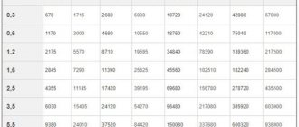
Calculation of the diameter of the water pipeline at 100 m3/h and flow speed v = 2 m/s.
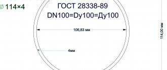
D = √ 354*100/2 = 133 mm. Selected nominal diameter DN 125 or DN 150.
b) Air under pressure
calculation of pipeline diameter for air at 600 m3/h, pressure 5 bar and flow speed 8 m/s.
Recalculation from normal flow rate 600 m3/h to working m3/h 600/5 = 120 m3/h.
D = √ 354*120/8 = 72 mm. Selected nominal diameter DN 65 or DN 80.
Depending on the purpose of water or air, a DN 65 or DN 80 pipeline is selected. It must be borne in mind that the calculation of the pipeline diameter is averaged and does not provide for the occurrence of peak load.
c) Saturated steam
Calculation of pipeline diameter for saturated steam at 1500 kg/h, pressure 16 bar and flow speed 15 m/s.
According to the steam table, the specific volume of saturated steam at a pressure of 16 bar is v = 0.1237 m3/kg.
D = √ 354*1500*0.1237/15 = 66 mm.
And here the issue of DN 65 or DN 80 must be resolved, depending on the possible peak load. If necessary, it is also possible to expand the installation in the future.
d) Superheated steam
If in our example the steam is overheated to a temperature of 300 °C, then its specific volume changes by v = 0.1585 m3/kg.
D = √ 354*1500*0.1585/15 = 75 mm, DN 80 is selected.
Image 4.9 in the form of a nomogram shows how a pipeline can be selected without performing a calculation. Figure 4-10 shows this process for the case of saturated and superheated steam.
e) Condensate
If we are talking about calculating a pipeline for condensate without steam (from unloading), then the calculation is carried out as for water.
Hot condensate after the condensate trap, entering the condensate pipeline, is unloaded there. Chapter 6.0 Condensate Handling explains how to determine the steam fraction of the discharge.
Rule for calculation:
Share of steam from unloading = (temperature before the steam trap minus steam temperature after the steam trap) x 0.2. When calculating the condensate pipeline, it is necessary to take into account the volume of steam from unloading.
The volume of remaining water in comparison with the volume of steam from unloading is so small that it can be neglected.
Calculation of the diameter of the condensate pipeline for a flow rate of 1000 kg/h of condensed steam 11 bar (h1 = 781 kJ/kg) and unloaded to a pressure of 4 bar (h' = 604 kJ/kg, v = 0.4622 m3/kg and r - 2133 kJ/ kg).
The share of unloaded steam is: 781 – 604/ 100% = 8.3%
Amount of unloaded steam: 1000 x 0.083 = 83 kg/h or 83 x 0.4622 -38 m3/h. The volume fraction of unloaded steam is about 97%.
Pipe diameter for the mixture at a flow speed of 8 m/s:
D = √ 354*1000*0.083*0.4622/8 = 40 mm.
For an atmospheric condensate network (v“ = 1.694 m3/kg), the share of unloaded steam is:
781 – 418/2258*100% = 16% or 160 kg/h.
In this case, the pipeline diameter is:
D = √ 354*1000*0.16*1.694/8 = 110 mm.
Source
: “Recommendations for the use of ARI equipment. A practical guide to steam and condensate. Requirements and conditions for safe operation. Ed. ARI-Armaturen GmbH & Co. KG 2010"
For a more accurate selection of equipment, you can contact us by email. email: [email protected]
STEAM MEASUREMENT, APPLIED METHODS AND STANDARDS
With all the variety of existing measurement methods, the choice of flow meters for steam metering is limited. In this article we propose to consider two main methods - using restriction devices and vortex flow meters.
The first method involves installing a restriction device (SU) in the pipeline. Mostly diaphragms are used as control systems, but it is also possible to use nozzles, Venturi tubes and other local hydraulic resistances.
As the flow passes through the diaphragm, the nature of its flow changes. Immediately before the constriction device, the pressure of the medium increases, and after it it decreases. The greater the difference in pressure before and after the diaphragm, the higher the flow rate.
The pressure of the medium, as well as its drop across the restriction device, is measured by methods and measuring instruments that meet the requirements of GOST 8.586.5. Steam metering by this method is also regulated by GOST R 8.586.1 - 2005, which, in particular, states that according to the conditions for using standard restriction devices, the controlled environment must be single-phase and homogeneous in physical properties (clause 6.2.2), and its the flow rate must be constant or vary slowly over time. (clause 6.3.1)
The second method using vortex flowmeters is based on the von Kármán effect. Behind the bluff body on both sides of the flow, alternate formation of vortices occurs. The frequency of vortex formation is proportional to the flow velocity. By measuring the pressure pulsation arising in the flow of vortices behind the bluff body, it is possible to determine the flow rate.
When metering steam with vortex flowmeters, in addition to the flow rate under operating conditions, it is also necessary to additionally measure the pressure and temperature of the medium. The measured parameters enter the heat calculator, which calculates the value of the mass of steam or thermal energy.
Note that to measure the mass of saturated steam, only one external sensor to choose from is sufficient, since a certain pressure value corresponds to a temperature value.
Table of temperature and saturated vapor pressure here
Algorithms for calculating the thermophysical properties of steam are prescribed in the methodology of the State Service for Standard Reference Data GSSSD MR 147-2008.
As a rule, as part of measuring instruments, the above algorithms belong to the computer or controller. However, in relation to vortex flowmeters of the EMIS brand, such algorithms are an integral part of the software of the electronic unit of the secondary converter of the meter itself - the flowmeter.
In accordance with the data of the algorithm, VORTEX 200 independently carries out corrections and calculations, thanks to the capabilities of an electronic unit with a computer function (“BB”), which provides for the connection of external pressure and temperature sensors.
The device calculates the following parameters: instantaneous and mass flow of steam, its density, enthalpy and accumulated energy.
Table: Parameters of calculation algorithms
It is important to note that when checking the “BB” function of the flow meter at the time of its release from production, this procedure must be carried out using a pressure and temperature sensor.
In addition to the built-in certified algorithms, in accordance with the GSSSD, the advantages of vortex flowmeters also include the following capabilities:
-remote data transfer, including wireless; - digital signal filtering; -simulation verification without removal from the pipeline; -free proprietary service and diagnostic software “EMIS”-Integrator.”
At the same time, it should be noted that, at the request or desire of the customer, a thermal energy metering unit “EMIS-Esko 2210” can be supplied, which will also include a calculator as a separate measuring instrument.
Why do you need a steam pipeline calculation?
The correct choice of the diameter of the steam pipeline ensures the correct and efficient operation of the steam-condensate system as a whole. If you select its dimensions “by eye”, you may encounter the following problems:
- A steam pipeline with a small diameter will provoke significant pressure losses, much lower than the calculated ones. The steam velocity will increase, which can lead to noise in the steam line. There may be an increase in the number of water hammers, which also need to be compensated, which means additional safety valves will have to be installed.
- Making the steam pipe too large in diameter will primarily increase the overall cost of the pipeline. In addition, this is fraught with increased heat losses to the environment and the formation of a significant amount of condensate, which means that more condensate drains, valves, steam separators, etc. will be required.
There are two ways to calculate the diameter of a steam line - the pressure drop method and the simpler velocity method.
STEAM CONVERTERS, TECHNOLOGICAL REQUIREMENTS
Considering the fact that the value of steam consumption often changes, depending on production volumes and other factors, the measurement range plays a significant role. For a vortex flowmeter this figure ranges from 1:20 to 1:40. If a restriction device is used as a measuring instrument, then, when combined with intelligent pressure sensors, its dynamic range with an error acceptable to the customer will be within 1:10. At the same time, the cost of the complex will be comparable to vortex flow meters.
Another important point that must be taken into account is the maximum steam temperature, which can be from +100 to +600 degrees. Differential pressure flowmeters are capable of operating over the entire designated range; the limit for vortex flowmeters is +450 degrees.
In this case, the device has design features and designs: a perforated stand, which prevents overheating of the converter, as well as two pressure pulsation sensors located behind the bluff body on both sides of it without protruding into the flow part. These sensors also contain piezoelectric elements that convert pressure pulsations into electrical signals.
As for the ambient temperature, vortex flowmeters are allowed to operate at -60 degrees, while in an unheated room, metering systems on a restriction device require increased attention: ensuring heating and purging of impulse lines to avoid freezing.
STEAM METERING UNITS BASED ON DIAPHRAGM
In 2021, the product line is expected to include measuring systems based on restriction devices, which use a diaphragm, which became a logical step in connection with the launch in 2021 of the production of intelligent pressure sensors “EMIS”-BAR.” Their main reduced error is from ±0.04%, which makes it possible to take into account the pressure drop method with the required accuracy.
At the request of customers, we are ready to supply fully equipped complexes, including a diaphragm, intelligent absolute and differential pressure sensors "EMIS"-BAR", a thermal converter, calibrated straight sections, flanges, impulse tubes, valve blocks, condensation and equalization vessels and other components for installation.
Steam metering units based on vortex flow meters.
As mentioned earlier, for steam measurement, at the customer’s request or request, we can supply measuring complexes “EMIS-Esco 2210” as a measuring instrument (included in the State Register of SI under No. 72830-18), which include: vortex flowmeter “EMIS”-VIKHR 200", pressure sensor "EMIS"-BAR", heat calculator and primary temperature transducer of an approved type.
When using the EMIS-Esko 2210 metering unit, which includes a controller, the previously listed advantages of vortex flowmeters are retained, but additional ones appear:
- archive with a depth of at least: hourly - 60 days, daily - 6 months, monthly - 36 months;
- real time clock;
- compliance with the Rules for commercial metering of thermal energy and coolant, approved by Decree of the Government of the Russian Federation of November 18, 2013 No. 1034 (hereinafter referred to as the Rules).
The best confirmation of the reliability of measurements using vortex flowmeters is many years of operating experience. In particular, EMIS-VIKHR 200 flow meters have been flawlessly performing coolant metering tasks at the Magnezit enterprise for more than 10 years. In his review, the customer notes that from 2010 to the present, three measuring units based on “EMIS”-VIKHR 200 devices have been used to measure superheated steam.” No comments were found regarding their work. During operation, flow meters have proven to be a reliable measurement tool that fully complies with the parameters declared by the manufacturer.
Positive feedback came from many customers, including specialists from the Ural Electrochemical Plant, part of the Rosatom state corporation:
“The service of the Chief Power Engineer of UEIP JSC has been using vortex flow converters “EMIS”-VIKHR 200” DN – 25, 50, 150 for more than 10 years at commercial steam metering units. The devices are installed both indoors and outdoors. Total quantity – 14 pieces. During operation, no comments were recorded regarding their work, and no negative verification results were noted.”