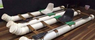
Welding of galvanized pipes in modern conditions is in demand in public utilities and the construction industry. The presented products are distinguished by their reliability and long service life, and are also one of the cheapest ways to install various types of communication networks. A zinc coating can protect metal elements from corrosion, which increases their service life. However, it is worth understanding whether welding is harmful to health, whether it is allowed for use and how it is carried out.
Since 2021, welding on galvanized steel is prohibited. So what will happen to our water pipes now?
Since 2021, welding on galvanized steel is prohibited. So what will happen to our water pipes now?
Sun Sep 02, 2021 11:38 am
4.6 Welding of steel pipes should be carried out by any method regulated by standards.
The types of welded joints of steel pipelines, the shape, and structural dimensions of the weld must comply with the requirements of GOST 16037.
The connection of steel pipes with a nominal diameter of up to 25 mm inclusive at a construction site should be carried out by lap welding (with one end of the pipe spreading or a threadless coupling). Butt joints of pipes with a nominal diameter of up to 25 mm inclusive can be performed at procurement plants.
When welding, threaded surfaces and flange surfaces must be protected from splashes and drops of molten metal.
The weld should be free of cracks, cavities, pores, undercuts, unwelded craters, as well as burns and leaks of the deposited metal.
Holes in pipes with a diameter of up to 40 mm for welding pipes must be made, as a rule, by drilling, milling or cutting out on a press.
The diameter of the hole must be equal to the internal diameter of the pipe with permissible deviations + 1 mm.
The use of welded connections of galvanized steel pipelines is not allowed. The method of connecting galvanized pipes is described in 5.1.2.
Until recently, galvanized pipes were the main ones for creating water supply networks in homes and industrial buildings. When laying pipe lines, welding was used on a large scale.
Even in places where, due to installation conditions, a welded connection is impossible, before installing the network element, a threaded end is welded to it for subsequent coupling connection.
To increase the service life of water and gas networks, pipes with a protective zinc coating are used. This does not lead to difficulties during the installation process, but the welding of galvanized pipes itself has a number of features that must be taken into account during the assembly process.
To understand the essence of the process, let’s consider what galvanized pipes are.
SNiP 3.05.04-85: Installation of pipelines
General provisions Earthwork
3.1. When moving pipes and assembled sections that have anti-corrosion coatings, soft pliers, flexible towels and other means should be used to prevent damage to these coatings.
3.2. When laying pipes intended for domestic and drinking water supply, surface water or waste water should not be allowed to enter them. Before installation, pipes and fittings, fittings and finished units must be inspected and cleaned inside and outside of dirt, snow, ice, oils and foreign objects.
3.3. Installation of pipelines must be carried out in accordance with the work project and technological maps after checking the compliance of the trench dimensions with the design, fastening the walls, bottom marks and, for above-ground installation, supporting structures. The results of the inspection must be reflected in the work log.
3.4. Socket-type pipes of non-pressure pipelines should, as a rule, be laid with the socket up the slope.
3.5. The straightness of sections of free-flow pipelines between adjacent wells provided for by the project should be controlled by looking “up to the light” using a mirror before and after backfilling the trench. When viewing a circular pipeline, the circle visible in the mirror must have the correct shape.
The permissible horizontal deviation from the circle shape should be no more than 1/4 of the pipeline diameter, but not more than 50 mm in each direction. Deviations from the correct vertical shape of the circle are not allowed.
3.6. The maximum deviations from the design position of the axes of pressure pipelines should not exceed ± 100 mm in plan, the marks of trays of free-flow pipelines - ± 5 mm, and the marks of the top of pressure pipelines - ± 30 mm, unless other standards are justified by the design.
3.7. Laying pressure pipelines along a flat curve without the use of fittings is allowed for socket pipes with butt joints on rubber seals with a rotation angle at each joint of no more than 2° for pipes with a nominal diameter of up to 600 mm and no more than 1° for pipes with a nominal diameter over 600 mm.
3.8. When installing water supply and sewerage pipelines in mountainous conditions, in addition to the requirements of these rules, the requirements of Section. 9 SNiP III-42-80.
3.9. When laying pipelines on a straight section of the route, the connected ends of adjacent pipes must be centered so that the width of the socket gap is the same along the entire circumference.
3.10. The ends of pipes, as well as holes in the flanges of shut-off and other valves, should be closed with plugs or wooden plugs during breaks in installation.
3.11. Rubber seals for installation of pipelines in conditions of low outdoor temperatures are not allowed to be used in a frozen state.
3.12. To seal (seal) butt joints of pipelines, sealing and “locking” materials, as well as sealants, should be used according to the design.
3.13. Flange connections of fittings and fittings should be installed in compliance with the following requirements:
flange connections must be installed perpendicular to the pipe axis;
the planes of the flanges being connected must be flat, the nuts of the bolts must be located on one side of the connection; The bolts should be tightened evenly in a cross pattern;
elimination of flange distortions by installing beveled gaskets or tightening bolts is not allowed;
Welding joints adjacent to the flange connection should be performed only after uniform tightening of all bolts on the flanges.
3.14. When using soil to construct a stop, the supporting wall of the pit must have an undisturbed soil structure.
3.15. The gap between the pipeline and the prefabricated part of the concrete or brick stops must be tightly filled with concrete mixture or cement mortar.
3.16. Protection of steel and reinforced concrete pipelines from corrosion should be carried out in accordance with the design and requirements of SNiP 3.04.03-85 and SNiP 2.03.11-85.
3.17. On pipelines under construction, the following stages and elements of hidden work are subject to acceptance with the preparation of inspection reports for hidden work in the form given in SNiP 3.01.01-85*: preparing the base for pipelines, installing stops, the size of gaps and making seals of butt joints, installing wells and chambers , anti-corrosion protection of pipelines, sealing of places where pipelines pass through the walls of wells and chambers, backfilling of pipelines with a seal, etc.
3.18. Welding methods, as well as types, structural elements and dimensions of welded joints of steel pipelines must comply with the requirements of GOST 16037-80.
3.19. Before assembling and welding pipes, you should clean them of dirt, check the geometric dimensions of the edges, clean the edges and the adjacent inner and outer surfaces of the pipes to a metallic shine to a width of at least 10 mm.
3.20. Upon completion of welding work, the external insulation of pipes at the welded joints must be restored in accordance with the design.
3.21. When assembling pipe joints without a backing ring, the displacement of the edges should not exceed 20% of the wall thickness, but not more than 3 mm. For butt joints assembled and welded on the remaining cylindrical ring, the displacement of the edges from the inside of the pipe should not exceed 1 mm.
3.22. The assembly of pipes with a diameter of over 100 mm, made with a longitudinal or spiral weld, should be carried out with an offset of the seams of adjacent pipes by at least 100 mm. When assembling a joint of pipes in which the factory longitudinal or spiral seam is welded on both sides, the displacement of these seams need not be made.
3.23. Transverse welded joints must be located at a distance of no less than:
0.2 m from the edge of the pipeline support structure;
0.3 m from the outer and inner surfaces of the chamber or the surface of the enclosing structure through which the pipeline passes, as well as from the edge of the case.
3.24. The connection of the ends of joined pipes and sections of pipelines with a gap between them greater than the permissible value should be made by inserting a “coil” with a length of at least 200 mm.
3.25. The distance between the circumferential weld seam of the pipeline and the seam of the nozzles welded to the pipeline must be at least 100 mm.
3.26. The assembly of pipes for welding must be carried out using centralizers; It is allowed to straighten smooth dents at the ends of pipes with a depth of up to 3.5% of the pipe diameter and adjust the edges using jacks, roller bearings and other means. Sections of pipes with dents exceeding 3.5% of the pipe diameter or having tears should be cut out. The ends of pipes with nicks or chamfers with a depth of more than 5 mm should be cut off.
When applying a root weld, the tacks must be completely digested. The electrodes or welding wire used for tack welding must be of the same grade as that used for welding the main seam.
3.27. Welders are allowed to weld joints of steel pipelines if they have documents authorizing them to carry out welding work in accordance with the Rules for Certification of Welders approved by the USSR State Mining and Technical Supervision.
3.28. Before being allowed to work on welding pipeline joints, each welder must weld an approved joint in production conditions (at the construction site) in the following cases:
if he started welding pipelines for the first time or had a break in work for more than 6 months;
if pipe welding is carried out from new grades of steel, using new grades of welding materials (electrodes, welding wire, fluxes) or using new types of welding equipment.
On pipes with a diameter of 529 mm or more, it is allowed to weld half of the permissible joint. The permissible joint is subjected to:
external inspection, during which the weld must meet the requirements of this section and GOST 16037-80;
radiographic control in accordance with the requirements of GOST 7512-82;
mechanical tensile and bending tests in accordance with GOST 6996-66.
In case of unsatisfactory results of checking a permissible joint, welding and re-inspection of two other permissible joints are performed. If, during repeated inspection, unsatisfactory results are obtained at at least one of the joints, the welder is recognized as having failed the tests and can be allowed to weld the pipeline only after additional training and repeated tests.
3.29. Each welder must have a mark assigned to him. The welder is obliged to knock out or fuse the mark at a distance of 30 - 50 mm from the joint on the side accessible for inspection.
3.30. Welding and tack welding of butt joints of pipes can be carried out at outdoor temperatures down to minus 50 °C. In this case, welding work without heating the welded joints is allowed to be performed:
at outside air temperatures down to minus 20 °C - when using pipes made of carbon steel with a carbon content of no more than 0.24% (regardless of the thickness of the pipe walls), as well as pipes made of low-alloy steel with a wall thickness of no more than 10 mm;
at outside air temperatures down to minus 10 °C - when using pipes made of carbon steel with a carbon content of over 0.24%, as well as pipes made of low-alloy steel with a wall thickness of over 10 mm. When the outside air temperature is below the above limits, welding work should be carried out with heating in special cabins, in which the air temperature should be maintained not lower than the above, or the ends of the welded pipes for a length of at least 200 mm should be heated in the open air to a temperature of at least 200 ° C.
After welding is completed, it is necessary to ensure a gradual decrease in the temperature of the joints and adjacent pipe areas by covering them after welding with an asbestos towel or other method.
3.31. When multilayer welding, each layer of the seam must be cleared of slag and metal spatter before applying the next seam. Areas of weld metal with pores, pits and cracks must be cut down to the base metal, and the weld craters must be welded.
3.32. When manual electric arc welding, individual layers of the seam must be applied so that their closing sections in adjacent layers do not coincide with one another.
3.33. When performing welding work outdoors during precipitation, the welding sites must be protected from moisture and wind.
3.34. When monitoring the quality of welded joints of steel pipelines, the following should be done:
operational control during pipeline assembly and welding in accordance with the requirements of SNiP 3.01.01-85*;
checking the continuity of welded joints with the identification of internal defects using one of the non-destructive (physical) control methods - radiographic (x-ray or gammagraphic) according to GOST 7512-82 or ultrasonic according to GOST 14782-86.
The use of the ultrasonic method is allowed only in combination with the radiographic method, which must test at least 10% of the total number of joints subject to inspection.
3.35. During operational quality control of welded joints of steel pipelines, it is necessary to check compliance with the standards of structural elements and dimensions of welded joints, welding method, quality of welding materials, edge preparation, size of gaps, number of tacks, as well as serviceability of welding equipment.
3.36. All welded joints are subject to external inspection. On pipelines with a diameter of 1020 mm or more, welded joints welded without a backing ring are subject to external inspection and measurement of dimensions from the outside and inside of the pipe, in other cases - only from the outside. Before inspection, the weld seam and adjacent pipe surfaces to a width of at least 20 mm (on both sides of the seam) must be cleaned of slag, splashes of molten metal, scale and other contaminants.
The quality of the weld according to the results of the external inspection is considered satisfactory if the following is not found:
cracks in the seam and adjacent area;
deviations from the permissible dimensions and shape of the seam;
undercuts, recesses between rollers, sagging, burns, unwelded craters and pores coming to the surface, lack of penetration or sagging at the root of the seam (when inspecting the joint from inside the pipe);
displacements of pipe edges exceeding the permissible dimensions.
Joints that do not meet the listed requirements are subject to correction or removal and re-control of their quality.
3.37. Water supply and sewerage pipelines with a design pressure of up to 1 MPa (10 kgf/cm2) in a volume of at least 2% (but not less than one joint for each welder) are subject to quality control of welded seams using physical control methods; 1 - 2 MPa (10-20 kgf/cm2) - in a volume of at least 5% (but not less than two joints for each welder); over 2 MPa (20 kgf/cm2) - in a volume of at least 10% (but not less than three joints for each welder).
3.38. Welded joints for inspection by physical methods are selected in the presence of a customer representative, who records in the work log information about the joints selected for inspection (location, welder's mark, etc.).
3.39. Physical control methods should be applied to 100% of welded joints of pipelines laid in sections of transitions under and above railway and tram tracks, through water barriers, under highways, in city sewers for communications when combined with other utilities. The length of controlled sections of pipelines at transition sections should be no less than the following dimensions:
for railways - the distance between the axes of the outer tracks and 40 m from them in each direction;
for highways - the width of the embankment at the bottom or the excavation at the top and 25 m from them in each direction;
for water barriers - within the boundaries of the underwater crossing determined by section. 6 SNiP 2.05.06-85;
for other utilities - the width of the structure being crossed, including its drainage devices, plus at least 4 m in each direction from the extreme boundaries of the structure being crossed.
3.40. Welds should be rejected if, upon inspection by physical control methods, cracks, unwelded craters, burns, fistulas, and also lack of penetration at the root of the weld made on the backing ring are detected.
When checking welds using the radiographic method, the following are considered acceptable defects:
pores and inclusions, the sizes of which do not exceed the maximum permissible according to GOST 23055-78 for class 7 welded joints;
lack of penetration, concavity and excess penetration at the root of a weld made by electric arc welding without a backing ring, the height (depth) of which does not exceed 10% of the nominal wall thickness, and the total length is 1/3 of the internal perimeter of the joint.
3.41. If unacceptable defects in welds are detected by physical control methods, these defects should be eliminated and the quality of a double number of welds should be re-controlled compared to that specified in clause 3.37. If unacceptable defects are detected during re-inspection, all joints made by this welder must be inspected.
3.42. Areas of the weld with unacceptable defects are subject to correction by local sampling and subsequent welding (as a rule, without overwelding the entire welded joint), if the total length of the sampling after removing the defective areas does not exceed the total length specified in GOST 23055-78 for class 7.
Correction of defects in joints should be done by arc welding.
Undercuts should be corrected by surfacing thread beads no more than 2 - 3 mm high. Cracks less than 50 mm long are drilled at the ends, cut out, thoroughly cleaned and welded in several layers.
3.43. The results of checking the quality of welded joints of steel pipelines using physical control methods should be documented in a report (protocol).
3.44. Installation of cast iron pipes produced in accordance with GOST 9583-75 should be carried out with sealing of socket joints with hemp resin or bituminized strands and an asbestos-cement lock, or only with sealant, and pipes produced in accordance with TU 14-3-12 47-83 rubber cuffs supplied complete with pipes without a locking device.
The composition of the asbestos-cement mixture for the construction of the lock, as well as the sealant, is determined by the project.
3.45. The size of the gap between the thrust surface of the socket and the end of the connected pipe (regardless of the joint sealing material) should be taken, mm, for pipes with a diameter of up to 300 mm - 5, over 300 mm - 8-10.
3.46. The dimensions of the sealing elements of the butt joint of cast iron pressure pipes must correspond to the values given in table. 1.
Table 1
| Nominal pipe diameter Dy, mm | Embedment depth, mm | ||
| when using hemp strands | when installing a lock | when using only sealant | |
| 65-200 | 35 | 30 | 50 |
| 250-400 | 45 | 30-35 | 60-65 |
| 600-1000 | 50-60 | 40-50 | 70-80 |
3.47. The size of the gap between the ends of the connected pipes should be taken, mm: for pipes with a diameter of up to 300 mm - 5, over 300 mm - 10.
3.48. Before starting the installation of pipelines, at the ends of the pipes being connected, depending on the length of the couplings used, marks should be made corresponding to the initial position of the coupling before installing the joint and the final position at the assembled joint.
3.49. The connection of asbestos-cement pipes with fittings or metal pipes should be carried out using cast iron fittings or steel welded pipes and rubber seals.
3.50. After completing the installation of each butt joint, it is necessary to check the correct location of the couplings and rubber seals in them, as well as the uniform tightening of the flange connections of the cast iron couplings.
3.51. The size of the gap between the thrust surface of the socket and the end of the connected pipe should be taken, mm:
for reinforced concrete pressure pipes with a diameter of up to 1000 mm - 12-15, with a diameter of over 1000 mm - 18-22;
for reinforced concrete and concrete non-pressure socket pipes with a diameter of up to 700 mm - 8-12, over 700 mm - 15-18;
for seam pipes - no more than 25.
3.52. Butt joints of pipes supplied without rubber rings should be sealed with hemp resin or bituminized strands, or sisal bituminized strands with the lock sealed with an asbestos-cement mixture, as well as polysulfide (thiokol) sealants. The embedment depth is given in table. 2, in this case, deviations in the depth of embedding of the strand and lock should not exceed ± 5 mm.
The gaps between the thrust surface of the sockets and the ends of the pipes in pipelines with a diameter of 1000 mm or more should be sealed from the inside with cement mortar. The grade of cement is determined by the project.
For drainage pipelines, it is allowed to seal the bell-shaped working gap to the full depth with cement mortar of grade B7.5, unless other requirements are provided for by the project.
table 2
| Diameter of nominal passage, mm | Embedment depth, mm | ||
| when using hemp or sisal strands | when installing a lock | when using only sealants | |
| 100-150 | 25 (35) | 25 | 35 |
| 200-250 | 40 (50) | 40 | 40 |
| 400-600 | 50 (60) | 50 | 50 |
| 800-1600 | 55 (65) | 55 | 70 |
| 2400 | 70 (80) | 70 | 95 |
3.53. Sealing of butt joints of seam free-flow reinforced concrete and concrete pipes with smooth ends should be carried out in accordance with the design.
3.54. The connection of reinforced concrete and concrete pipes with pipeline fittings and metal pipes should be carried out using steel inserts or reinforced concrete shaped connecting parts made according to the design.
3.55. The size of the gap between the ends of the ceramic pipes being laid (regardless of the material used to seal the joints) should be taken, mm: for pipes with a diameter of up to 300 mm - 5 - 7, for larger diameters - 8 - 10.
3.56. Butt joints of pipelines made of ceramic pipes should be sealed with hemp or sisal bituminized strands, followed by a lock made of B7.5 cement mortar, asphalt (bitumen) mastic and polysulfide (thiokol) sealants, unless other materials are provided for in the project. The use of asphalt mastic is allowed when the temperature of the transported waste liquid is no more than 40 °C and in the absence of bitumen solvents in it.
The main dimensions of the elements of the butt joint of ceramic pipes must correspond to the values given in table. 3.
Table 3
| Diameter of nominal passage, mm | Embedment depth, mm | ||
| when using hemp or sisal strands | when installing a lock | when using only sealants or bitumen mastic | |
| 160-300 | 30 | 30 | 40 |
| 350 — 600 | 30 | 38 | 45 |
3.58. The connection of pipes made of high-density polyethylene (HDPE) and low-density polyethylene (LDPE) with each other and with fittings should be carried out with a heated tool using the method of butt or socket welding. Welding pipes and fittings made of different types of polyethylene (HDPE and LDPE) together is not allowed.
3.59. For welding, installations (devices) should be used that ensure the maintenance of technological parameters in accordance with OST 6-19-505-79 and other regulatory and technical documentation approved in the prescribed manner.
3.60. Welders are allowed to weld pipelines made of LDPE and HDPE if they have documents authorizing them to carry out work on welding plastics.
3.61. Welding of pipes made of LDPE and HDPE can be carried out at an outside air temperature of at least minus 10 °C. At lower outside temperatures, welding should be done in insulated rooms.
When performing welding work, the welding site must be protected from exposure to precipitation and dust.
3.62. The connection of polyvinyl chloride (PVC) pipes to each other and to fittings should be carried out using the socket gluing method (using GIPC-127 glue in accordance with TU 6-05-251-95-79) and using rubber cuffs supplied complete with the pipes .
3.63. Glued joints should not be subjected to mechanical stress for 15 minutes. Pipelines with adhesive joints should not be subjected to hydraulic tests within 24 hours.
3.64. Gluing work should be carried out at an outside temperature of 5 to 35 °C. The work place must be protected from exposure to precipitation and dust.
Pipeline crossings through natural and artificial barriers Water supply and sewerage structures Additional requirements for the construction of pipelines and water supply and sewerage structures in special natural and climatic conditions Testing of pipelines and structures Appendix 1 Appendix 2 Appendix 3 Appendix 4 Appendix 5 Appendix 6
Galvanizing metal as a method of corrosion protection
Protective coating of steel products has been used for a long time, since non-ferrous metals that are resistant to corrosion are too expensive for the manufacture of solid products from them. And the strength properties of such objects are very low. Tinning on the surface with tin or copper plating was used to create a protective film.
Galvanizing has become popular due to the increased adhesion of zinc to iron. The melting point of this metal is 900 – 920 o. In a liquid state, it, applied to the surface of a steel product, forms a durable protective film several microns thick that successfully resists corrosion.
Today, three main methods of applying a protective coating are used:
- Galvanic. In this case, zinc ions are deposited on the surface of a steel product connected to the opposite electrode in a galvanic bath. They are firmly attached to the surface of the product, creating a virtually indestructible protective film. The thickness of the protective layer is regulated by the processing time, which allows rational use of expensive non-ferrous metal, in particular zinc.
- Spraying method. Its essence is to apply sprayed metal to the surface using a special gun, in which the sprayed substance melts. Then this substance is jetted onto the surface to be treated, covering it with a protective layer.
What is the difference between galvanized pipes and ordinary ones?
About 60% of the zinc extracted from the bowels of the earth by the mining industry is used in the production of galvanized rolled products, another 20% is used for galvanizing metal structures (automotive and industrial equipment bodies, building materials), machine parts and mechanisms.
The difference between structural steel and non-corrosion metals (tin, aluminum, lead, zinc) is that the latter, when oxidized in air, forms an oxide, which in the form of a protective film becomes a barrier to the access of oxygen to the metal. Thus, the film prevents further oxidation and protects the metal from corrosion destruction. Iron, unlike non-ferrous metals and alloys, during corrosion forms a loose hydroxide of large volume, as a result of which oxygen easily penetrates to its surface and the oxidation process continues.
The zinc coating applied to the surface of the steel protects the iron from contact with oxygen - thus, its corrosion protection is significantly increased and the galvanized product can be used for an average of about 50 years.
The essence of the technology is that, from an electrochemical point of view, iron forms a galvanic couple with zinc, in which the more active zinc enters into a corrosive interaction with oxygen first, leaving the iron in a chemically passive state. In a similar way, you can significantly accelerate the corrosion of iron if you apply tin, which is a more passive element in a galvanic pair with iron, to its surface and damage its shell.
Metal pipes made of any grade of steel are subjected to galvanization, covering not only their outer but also the inner surface, while the highest quality and homogeneous layer is obtained in seamless rolling. Various technologies are used to apply zinc, which can be used not only on an industrial scale, but also in small private production - many commercial companies are engaged in galvanizing steel parts to order.
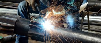
Welding connection
This type of joining of pipes during the installation of heating, plumbing and gas systems is stipulated by a number of regulatory documents, one of which is SNiP 3.05.01-85 “Internal sanitary and technical systems”.
When welding galvanized pipes, SNiP, mentioned above, indicates the need to comply with the requirements of a number of standards that determine the order of use of materials and regulate the work process. In particular, when welding galvanized pipes, GOST 16037-80 regulates the use of certain types of welded joints, the shape and design features of the seams, as well as other requirements for them.
When flame welding, you need to use self-shielding welding wire of the Sv 15GSTYUTSA brand, which contains the element selenium. Wire size from 0.8 to 1.2 mm.
It is also possible to make connections using electrodes for welding galvanized pipes with grades containing fluorine-calcium or rutile compounds in the coating. Their diameter is selected in accordance with the wall thickness of the parts being welded, the maximum size is 3 mm in diameter.
Creating a pipeline network involves pre-assembly in blocks, with part of the operation performed at a plant that performs a series of pre-assembly activities for the assembly blocks. At the same time, the regulations provide for the use of local air suction systems to remove combustion products of zinc coating that are hazardous to health.
The technology for welding galvanized pipes also involves stripping the surface of the protective coating at a distance of 30 - 40 mm from the end. After processing the weld, it is necessary to restore the corrosion protection at the joint.
For this purpose, paint of a special composition is used, consisting of 95% fine zinc powder and containing synthetic binders in the form of epoxy resins, synthetic rubber or polystyrene.
The joining of water and gas pipes with a protective zinc coating (and without it), having a nominal bore of up to 25 mm, should be done “overlapping”, for which purpose one end is first expanded.
When welding, the threaded ends of pipes, as well as flange mirrors, need protection from drops of hot metal formed during the welding process.
The following defects are not allowed in the weld:
- shells;
- cracks;
- undercuts;
- pores;
- uncooked craters;
- burns and metal leaks.
Ultrasonic inspection of welds is not used; their integrity is checked when the system is pressurized with a certain pressure.
A method has been developed for joining galvanized workpieces by welding using flux. This substance makes it possible to obtain a viscous, airtight layer that prevents oxidation (burnout) of the zinc cladding layer.
Flux for welding galvanized pipes is brought into a liquid-viscous state and applied to the joint of the parts being connected. During the welding process, it still melts, covering the area along the seam with a thin layer, preventing the zinc layer from peeling off and burning.
When using flux, damage to the protective layer may occur when it was applied by hot-dip galvanizing.
This becomes possible with the slightest deviation from the requirements of the technological process during coating or welding.
The penetration of flux into the internal cavity of the pipeline is not dangerous, since it easily dissolves in water and is washed out at the stage of pressure testing of the pipeline.
There is a method of connecting galvanized pipes called welding and soldering. For this, a filler rod is used, which contains elements such as zinc, copper, silicon and tin. The process technology is as follows:
- the butt ends are heated to the melting temperature of the filler rod, which is 900 - 950 o;
- the filler rod is placed between the chamfers of the parts being welded;
- a layer of flux is poured onto the seam in such a way that it covers the surface for a distance of up to 20 mm on the sides of the seam;
- the additive is heated with a burner until completely melted, while it creates a reliable connection of pipes without damaging the zinc cladding coating.
Selecting Electrodes
As already mentioned, the welding process is accompanied by the release of thermal energy, so the zinc begins to evaporate intensively.
There is a high probability that this metal will end up in the weld pool and mix with the steel. And this will lead to the formation of pores and cracks at the level of steel crystallization, and, as a consequence, to a decrease in the quality of the joint of the connected products. Therefore, the main requirement for welding galvanized pipes is the removal of the zinc layer in the joint area.
If it is not possible to remove the protective coating, then special electrodes are used to connect galvanized pipes . In principle, welding a galvanized product is practically no different from the same process of joining ordinary steel. But there are also some nuances.
Firstly, the welding electrode itself is a metal rod coated with powder. It is the type of powder layer that influences what metals can be welded.
In the case of welding galvanized pipes, electrodes with either rutile or basic coating are used. The first is used if the pipes are made of carbon steel (for example, steel 20), the second if they are made of low-alloy steel (C345).
Rutile coating
Electrodes with rutile coating are used. Rutile is a mineral in the form of titanium oxide. It is powder coated and used as a concentrate with a content of more than 50%. The composition also includes aluminosilicates and carbonates.
The slag obtained during welding has high alkalinity, so the metal of the joint has such characteristics as high impact strength and increased protection against the formation of hot cracks.
The only requirement for rutile electrodes for welding galvanized pipes is to dry them for an hour at a temperature of +200 °C before starting the process. But you can use consumables only after a day.
Basic coating
Basic coated electrodes can be used. This powder layer has a complex formulation, which includes a large number of different chemicals: magnesium, calcium, fluorspar and ferroalloys.
When burned inside the welding zone, the powder releases carbon dioxide and carbon monoxide, which protect the molten metal from oxygen and hydrogen. The last two reduce the quality of welding. Typically, these electrodes are used to weld pipelines made from thick-walled pipes.
Is welding of galvanized pipes allowed?
This operation is used during the installation of gas, plumbing and heating systems. It is regulated by a number of documents:
- One of the most important is SNiP 3.05.01-85 “Internal sanitary systems”. In accordance with it, in the process of welding pipes of the type in question, it is necessary to fulfill the requirements set out in a number of standards. They are aimed at determining the order of use of materials and regulating the work process.
- In turn, GOST 16037-80 indicates the use of specific types of welded joints, design features of seams and other important requirements.
- In accordance with SP 73.13330.2012, galvanized pipes and other metal components must be connected on threads using galvanized connecting parts: on flanges, union nuts or press fittings. However, this condition is only a recommendation and not a mandatory requirement.
When flame welding, it is necessary to use a special welding wire of the Sv-15GSTYUTSA brand, which has a diameter of 0.8 to 1.2 mm, and also contains selenium as one of the components. It is permissible to make connections using electrodes that contain rutile or V300 ring connections in the coating. The diameter must be selected depending on the wall thickness of the components being connected.
TEST METHODS
4.1. For quality control, one sample is cut from each selected pipe for each type of test.
The tensile test is carried out in accordance with GOST 10006. Instead of the tensile test, it is allowed to control the mechanical properties by non-destructive methods.
(Changed edition, Amendment No. 3, 6).
4.2. The surface of the pipes is inspected visually.
4.3. Hydraulic testing is carried out in accordance with GOST 3845 with exposure to test pressure for at least 5 s.
4.4. The bend test is carried out according to GOST 3728. Galvanized pipes are tested before coating.
(Changed edition, Amendment No. 3).
4.4a. The expansion test is carried out according to GOST 8694 on a conical mandrel with a cone angle of 6 °.
Testing on a mandrel with a taper angle of 30° is permitted.
(Changed edition, Amendment No. 3, 4).
4.4b. The flattening test is carried out according to GOST 8695.
(Changed edition, Amendment No. 3).
4.4v. Weld inspection is carried out using non-destructive methods according to regulatory and technical documentation.
(Introduced additionally, Amendment No. 3).
4.5. The thickness of the zinc coating on the outer surface and in accessible places on the inner surface is controlled according to GOST 9.301 and GOST 9.302, as well as with devices of the MT-41NTs, MTZON or Impulse type according to the normative and technical documentation.
In this case, the screw-in of the no-go ring gauge onto the thread should be no more than three turns.
(Changed edition, Amendment No. 3, 4).
(Changed edition, Amendment No. 3, 5).
4.8. The right angle of the pipe ends is controlled with a 90° square measuring 160 ´ 100 mm, class 3 GOST 3749, plate probes set 4 according to ND or an inclinometer GOST 5378. The bevel angle of the chamfer is controlled with an inclinometer in accordance with GOST 5378.
(Changed edition, Amendment No. 3, 6).
The wall thickness, the height of the internal burr and the height of the burrs are measured with a micrometer according to GOST 6507-90 or a wall gauge according to GOST 11358 at both ends of the pipe.
The length of the pipes is measured with a tape measure in accordance with GOST 7502. The threads are controlled with gauges in accordance with GOST 2533.
The mass of a batch of pipes is controlled on scales of no more than 10 tons with a division value of no more than 20 kg.
(Changed edition, Amendment No. 3, 4, 5, 6).
4.10. Weld inspection is carried out using non-destructive methods according to technical documentation.
(Introduced additionally, Amendment No. 4).
Security measures
In the process of creating a pipeline network, it is necessary to pre-assemble the mounting blocks. Welding must be carried out in a room in which air exhausts are used to eliminate combustion products of the zinc coating. In other conditions, work is strictly prohibited , as it will be hazardous to health.
When welding galvanized pipes, the following rules must be followed:
- Carrying out work requires ensuring that the zinc does not overheat. This will provide effective protection against corrosion.
- Places intended for connecting pipes must first be protected to a shine and degreased. They also have a flux layer applied to them, which helps protect the metal.
- The burner should be 1-2 numbers smaller than a similar device for steel products.
- If gas welding is used, the flame must be set so as to leave a slight excess of oxygen.
- The workpieces are preheated to a greater width than the connecting point.
- A rod with a special coating is installed at the joint and melted by a burner fire, which should be directed directly at it, and not at the material.
- Flux is removed upon completion of welding work.
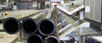
Methods of galvanizing steel
For galvanizing rolled pipes, specialists have developed several methods that differ significantly in the application process, layer thickness and coating quality. Galvanized pipes, unlike base rolled steel, have better corrosion resistance, but their physical characteristics are no different from steel products, so they are subject to standards for gas and electric welded pipes.
Rice. 2 Hot-dip galvanizing
Hot galvanizing
Coating steel surfaces inside and outside with molten hot zinc is the most common method for pipes up to 8 meters in length; the technology is widely used in the national economy at large machine-building enterprises.
For galvanizing in a factory, during the preparation of products, degreasing with alkalis and etching in solutions of sulfuric and hydrochloric acids are used; for fluxing, solutions of ammonium chloride or zinc are heated to 40 - 50º C. The further process consists of lowering the pipes into a bath of zinc melt at a temperature of 460º C - the zinc binds with oxygen, and the resulting ZnO oxide, after reacting with carbon dioxide CO2, forms a protective film of ZnCO3 carbonate.
This gray material has a matte surface, high mechanical hardness and adhesive strength, distinctive features of hot-dip galvanizing (HZ):
- The standard thickness of the zinc layer is 50 - 70 microns on the outer surface and 80 - 100 microns on the inner surface; if damaged, it is capable of self-healing.
- Corrosion resistance is close to stainless alloys, the service life of coatings on rolled metal in the industrial sector is 65 years, outside the city - up to 120 years, when using galvanized pipelines for water supply in heating systems, their service life is 15 - 25 years.
- Low-carbon steel pipes with a diameter of 17 - 160 mm and a length of 6 to 12 m are hot coated with zinc.
- The main disadvantage of the method is some unevenness of the layer (sagging) along the length and perimeter of the pipes.
Rice. 3 Galvanized
Related article:
How to weld a pipe with water - several proven options . Reading about how to weld galvanized pipes, it may be interesting to read about how you can weld a pipe with water. Sometimes it is very necessary to do something when a pipe is leaking and you can’t turn off the water.
Galvanic (electrolytic) galvanizing method
The technology occupies a leading position in the coating of various types of parts of complex shapes; dissolved zinc has an electrochemical effect on the metal surface, which, through an electrolytic solution, enters the parts being processed and is deposited on their surface. To do this, a steel element (cathode) is placed in a bath with an electrolyte, zinc plates (anode) are placed at the other end and a direct current is supplied to them, with a negative potential on the part and a positive potential on the zinc plate.
Electrolytic galvanizing technology (EC) has the following features:
- Depending on the time the workpiece is in the electrolytic environment, the thickness of the zinc layer can be adjusted, which is usually 20 - 30 microns.
- The products have a beautiful decorative appearance with a glossy surface of silver, bluish or yellow tint; with some technologies they also obtain a matte finish.
- Using the electrolytic method, it is possible to spray metal parts combined with elements made of other materials on which zinc is not deposited (plastics).
- The disadvantages of the method include insufficiently high adhesion and the need to dispose of the used electrolyte with a high concentration of hazardous chemical waste - as a result, the cost of the electrolytic method is higher.
Rice. 4 Chambers for TDC sputtering
Thermal diffusion galvanizing (TDG) by spraying
The technology is based on the diffusion deposition of zinc, which is in a vapor state and heated to a high temperature, into the protected steel surface. To do this, the workpiece is placed in special processing equipment - a hermetically sealed chamber, and a temperature of 290 - 450º C is created in it (the method is called sherardization), while the powdered zinc goes into a gaseous state and its atoms diffuse into the surface layer of the part.
Another type of technology is the processing of parts in zinc vapor at temperatures of 800 - 900º C, distinctive features of the methods:
- High cost, almost twice as much as that of hot-dip galvanizing technology. • Possibility of adjusting the thickness of the protective layer in a wide range, the average value of which is about 40 microns.
- The protective coating has a dense structure and high adhesion to the steel surface, its protective properties are 5 times higher than those of galvanic galvanization.
- The technology is environmentally friendly, since the process takes place in a closed chamber, and there are no harmful emissions into the atmosphere or sewer system.
- The disadvantages include the not very aesthetic appearance of the products, having a dirty gray color, low productivity and heterogeneity of the coating.
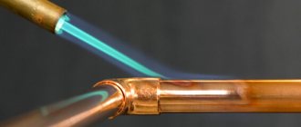
Rice. 5 Gas-thermal coating method
Thermal spraying
This technology is used to apply a protective zinc coating to parts that need to be protected or repaired at any location. The essence of the method is to apply zinc, in powder form or in the form of a cord or solder, to the surface of the workpiece by placing it in the gas jet of a burner. Particles of gaseous molten zinc, hitting a steel surface heated to a temperature of no more than 150º C, form a shell on it in the form of scales, protecting the iron from corrosion.
Unlike GC coatings, thermal spraying chips more easily and does not have the ability to self-heal in damaged areas. Typically, products galvanized by this method are coated with paints and varnishes; the thickness of the zinc layer reaches 200 microns or more.
Cold galvanizing
The technology has gained popularity recently; it is successfully used in everyday conditions - processing does not require special equipment or the use of complex technical processes. The essence of the process is that a zinc-containing composition (Zinconol, Galvanol) with 89 - 93% zinc is applied to the surface to be treated, using an ordinary construction brush, roller or spray gun; the drying process of one layer takes no more than 30 minutes.
The method is convenient to use in cases where the metal structure cannot be moved or dismantled; car enthusiasts use cold galvanizing for body repairs. Disadvantages include low resistance to mechanical stress and petroleum products (gasoline, kerosene, machine oils).
Rice. 6 Cold galvanizing
Submerged Welding Technology
This technology is one of the most suitable options. The presented substance provides a viscous layer that does not allow air to pass through. As a result, oxidation of the zinc layer is prevented.
Before directly using flux for welding, it must be brought into a liquid state. The substance is applied to the areas of the elements being connected. When welding, the material will melt, thereby covering the entire desired area with a thin layer, which will prevent zinc peeling.
Often, specialists encounter damage to the protective layer when applying it using the hot-dip galvanizing method. This happens even with minor deviations from the established process requirements. It is worth noting that it is safe for flux to get inside the pipeline, since it easily dissolves in water and will be washed out at the crimping stage.
The pipe connection is made as follows:
- The butt ends are heated to a temperature of 900-950 o.
- A rod containing copper, zinc, tin and silicon is placed between the chamfers of the elements being welded.
- A layer of flux is poured onto the seam site, which should cover the surface up to 20 mm on the sides of the seam.
- The additive is heated with a burner until it melts, and this ends the procedure.
Compliance with the requirements of the welding process, the use of high-quality materials and equipment guarantee a reliable connection of galvanized pipes ready for use.
The final stage and subsequent processing of the joint
Welded galvanized pipes have a seam that is not protected from corrosion; when welding with gas torches, a significant area of galvanization around the joint burns out - all this leads to poor corrosion resistance of the joint. Before and after completion of welding, processing and smoothing the seam with abrasive materials, the following methods are used to combat corrosion:
- When welding using gas torches, rods made of corrosion-resistant stainless materials (zinc-cadmium, brass) are used.
- To protect the external surface, thermal spraying of zinc or a coating of zinc-containing materials in the form of paint is used.
It should be noted that these methods are effective when using a galvanized pipeline for gas supply; if a coated welded pipe is installed in a heating system, then the zinc layer burned out from the inside no longer protects its surface, and corrosion will occur quite quickly. Therefore, when using zinc pipes for heating, he uses other modern methods of connecting them using fittings.
Rice. 14 Solder-welding connection of parts to a zinc metal surface - appearance
Electric arc welding, selection of electrodes
Electric arc welding makes it possible to ensure a reliable connection of the pipelines in question. The efficiency of the process is achieved with the correct choice of welding machine and suitable electrodes. In this case, the connection material has a significant influence on the choice of tool. It is important to use a semi-automatic device.
Welding galvanized metal has its own nuances. The process must be carried out quickly so that the zinc does not have time to evaporate from the joint area. The technological condition under consideration can only be provided by electrodes with a rutile coating. They have a special chemical composition, which ensures their rapid ignition. At the time of welding, a welding arc is formed, which allows the formation of high-quality connecting seams. If the procedure is carried out correctly, they will not contain pores. The advantage of rutile electrodes also consists in a small coefficient of spattering of molten metal, which is important when working with galvanized material.
Manufacturers can add a small amount of iron powder to the rutile coating. This helps reduce the specific gravity of carbon and increases the material’s resistance to cracking. It is necessary to select the size and voltage of the electrodes depending on the thickness of the pipes.
Connection without welding
Taking into account the fact that welding of galvanized pipes is not recommended and can only be carried out by professionals under special conditions , the use of connection methods through the installation of special fasteners becomes relevant. These include couplings, nuts, traditional and compression fittings. They allow for reliable fastening of pipes made of different materials and having different diameters. The construction market offers a wide range of products of this type, which can be selected according to material, size, reliability and other technical characteristics.
Another method is a threaded connection. However, its use is allowed only in those places of the pipeline in which it is possible to control the reliability of the connection and carry out repairs.