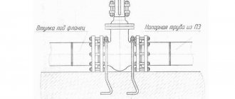
Pipeline under the road
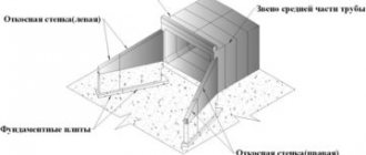
We continue to introduce our readers to prefabricated reinforced concrete, without which neither residential, industrial, nor transport construction can exist today, and we would like to draw your attention to concrete road pipes. These are not products, but structures intended for laying under embankments of railways and highways, and assembled from individual links. That's what we'll talk about.
Reinforced concrete culverts
One of the main advantages of reinforced concrete structures for water drainage is the ability to create them at the place where they will be installed. The arrangement process in this case involves the installation of reinforced formwork into which the concrete solution will be poured.
The quality described above can be called quite useful, but it has a serious drawback - a reinforced concrete culvert under the road takes a very long time to install. Of course, there is a solution to this problem, which consists in purchasing ready-made reinforced concrete structures and delivering them to the installation site. The main quality of such a material is its ability to withstand the effects of various external factors.
Reasons for installing a drainage system
In the list below you will find the three most common reasons that force property owners to turn to a drainage system.
- Clay soil. This problem is very common, since clay soils create excess water in the area.
- Swampy soil.
- The slope of the terrain, which creates a destructive flow of water. Such a flow can wash away the fertile layer of the earth.
If your site is located in a swampy area or the soil has a predominant percentage of clay, you should pay attention to drainage.
Plastic Culverts
Various options for polymer products for arranging culverts are a good solution. Plastic pipes can withstand external loads well, but to do this they have to be further strengthened using a concrete arch, which is poured along the outer edge of the pipe, and the weak resistance of concrete to soil movements in this case does not matter at all.
If necessary, you can reduce the load on the system by using special metal boxes filled with stones. A drainage pipe installed under the road in this way combines reliability and durability - the service life of a plastic culvert can reach 50 years.
Tools you will need for the job
Before answering the question “how to drain roads,” you need to understand the tools you can’t do without. Open and closed systems require their own set of tools and materials.
For open drainage you will need:
- shovel;
- materials with which it will be possible to strengthen the slopes (concrete, stone or others);
- seeds of wild herbs.
For closed drainage you will need:
- shovel;
- geotextiles;
- crushed stone;
- drainage mats or pipes.
If you are using a linear drainage system, then use the following set of tools and materials:
- concrete;
- shovel;
- drainage trays.
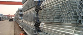
Metal pipes and SMGK
Metal culverts are a good option for solving the problem of water drainage, but only if you look at it from one side. Metal structures have better strength indicators compared to analogues, but this advantage is completely offset by poor corrosion resistance. Because of this, metal pipes are used to construct culverts only temporarily.
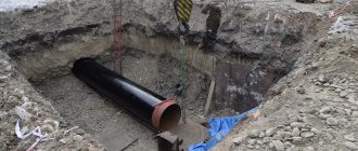
However, there is another use for metal products. They are often used to puncture road surfaces. The fact is that it is not always possible to repair the water pipeline running under the road, so the pipe is cleared using an external drainage system, which allows for repairs or high-quality cleaning of the system.
A good solution is to use metal pipes as an external protective casing to protect the main pipeline. Typically, pipes used for reinforcing the walls of boreholes are used for these purposes.
To create a reliable and high-quality culvert, it is best to use SMGC - prefabricated metal corrugated structures. According to the general classification, such structures are not ordinary pipes - a complete system becomes such only in the place where it is necessary to install culverts.
SMCs have a lot of positive qualities that simple pipes lack. The main advantage of a prefabricated structure is the possibility of constructing complex structures that can last for several decades and at the same time calmly survive the effects of seismic shifts. Corrugated road pipe, among other things, costs almost a third less than alternative options.
Design features of drains
The main design difference between drainage pipes for draining groundwater is the presence or absence of perforation and its type. There are partially and fully perforated drain pipes. In the first case, the holes are not located on the entire surface of the product. In the second, they are located throughout the part. This difference is explained by the scope of application of perforated elements. Let's look at what types of drainage pipes there are according to the type of perforation.
Types by type of perforation
- 120°. The holes are located in the upper third of the product. Used in areas with low humidity.
- 180°. Half of the part is perforated. It is used in areas where the amount of rain and melt water prevails over groundwater.
- 240°. The lower third of the drain remains intact, the upper thirds are perforated. Used to drain water on slopes and in areas with different types of soil.
- 360°. Full perforation. Used in areas with severe flooding.
Depending on the installation depth, single- and double-layer drainage pipes are used. Single-layer products are designed for depths up to 3 m. These are models of strength classes SN2 and SN4. The first are laid no deeper than 2 m, the second - to a depth of no more than 3 m. Two-layer drains are more durable, hardness class - SN6. The outer layer is made corrugated to better withstand loads. The inner one is smooth, which facilitates the movement of liquid.
Drain pipes are manufactured in rigid and flexible versions. Rigid parts are divided into segments no longer than 4 m and laid using special adapters. They are needed to perform turns, bends, etc. Flexible elements have a stiffness class of SN8 and are easily bent in the desired direction. Stacked to a depth of up to 10 m.
Instagram pipelife_ukr
- Water supply and sewerage
3 ways to eliminate and prevent blockages in outdoor drains
Installation of culverts under the road
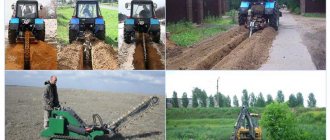
The technology for constructing drainage channels under the road includes several stages:
- Preparing the pit.
- Pouring the foundation.
- Pipeline laying.
- Construction of a road embankment.
The first step is to dig a pit, the dimensions of which coincide with those calculated during the design. It is also important to take into account the soil that prevails on the site - unsuitable soil may prevent the construction of a heavy structure. In addition, the type of soil directly affects how the walls of the pit will be constructed.
Site analysis
A method for diagnosing soil moisture absorption. Dig a small hole, up to half a meter deep, and fill it with water. If all the moisture goes into the ground within a day, then natural drainage will be quite enough. If the water remains at the same level or decreases slightly, additional drainage is required.
Before starting work on installing a drainage system, you should draw a plan for the drainage system and calculate its slope. This can be done using a map, using the altitude points marked on it. If there is none, watch the rainwater: where it flows, that’s where the drainage system should be directed.
With a flat surface of the site, the depth of laying the drainage of the site should be gradually increased towards the final section of the drainage. If the building is located on a hill, then ditches of equal depth are dug towards the natural slope.
The depth of drainage structures is set in accordance with the intended tasks. Namely:
- To drain rainwater from the site, shallow grooves of 10-15 cm are suitable.
- To dehydrate the soil surface to improve the growth of flowers and shrubs, you need to choose a backfill or closed type method, in which the drainage depth is provided from 40 to 60 cm.
- If we are talking about the well-being of fruit trees growing in an excessively wet area, then it is necessary to arrange the drainage in such a way that it removes excess water from the roots of the plants. For small trees, the drainage depth is up to 1.2 meters.
- Only a closed drainage system can protect the foundation and the building itself from the negative effects of moisture. In this case, the depth directly correlates with the thickness of the foundation: the minimum occurrence of the drainage pipe is half a meter from its base.
Drains need to be laid along the entire perimeter of the territory. The drainage depth on the site is calculated based on the level of soil freezing in winter and the depth of the building foundation. The data is presented in the tables below.
How to strengthen a drainage ditch?
You can strengthen the drainage ditch in the following ways:
- sow wild herbs on slopes;
- reinforce with concrete slabs and stones;
- create a lattice of concrete or stone, and also sow herbs;
- secure the geogrid.
If drainage laying from special trays will be installed, then dig a ditch 10 cm in advance, that is, 5 cm above the tray. A concrete pad is poured at a depth of 10 cm, and then trays are laid out on it. But, it is important to wait until the concrete hardens. The space that remains must be filled with cement. Next, a storm grate is placed on the trays.
If you are using a closed system, the width must be at least 30 cm and the depth must be sufficient for laying pipes or mats. Next, the material is laid and filled with crushed stone. Do not forget about geotextiles, which can protect the structure from the ingress of unwanted soil.
VI. Design of subgrade with partial peat removal
41. Subgrade with partial peat removal should be prescribed in the following cases:
a) if the density of the peat deposit increases in depth;
b) if at a certain depth of the swamp there is a layer of high stumpiness that does not allow the use of other types of subgrade structures;
c) in order to accelerate the consolidation of the foundation.
The same requirements apply to the subgrade with partial peat removal as to floating embankments /ch.
42. The minimum depth for replacing peat with high-quality mineral soil should be such that the total thickness of the bulk layer from the top of the remaining peat layer to the design level is no less than that required according to Table. .
43. The stability of the embankment base against extrusion during partial peat removal should be checked using the Gersevanov-Puzyrevsky formula:
where: Rbez -
the value of the specific load does not cause plastic deformation of the base;
IN
— width of the embankment at the base;
— volumetric weight of the embankment material;
— volumetric weight of peat in its natural state;
h in
— depth of peat removal;
j
and C
are the angle of internal friction and cohesion of peat according to laboratory data.
44. The amount of settlement of the embankment with partial peat removal due to the compaction of the remaining layers of peat is determined in the same way as for a floating embankment /p. /.
45. The duration of intensive settlement of the embankment due to the consolidation of foundation soils is determined in the same way as for a floating embankment /p. 82/.
With partial peat removal, the rate of consolidation of the base increases in proportion to the square of the ratio of the total depth of the bog to the thickness of the removed peat.