Threaded connections are connections between constituent structural elements made using fasteners - bolts, screws, nuts and studs. Various types of washers are used as additional components: flat, single-turn or double-turn spring, claw, toothed and others. The thread on the parts involved in detachable fixed connections is called fastening or fastening-sealing. It is performed by applying helical grooves with the corresponding cross-section of their profile to the outer or inner surface of the parts. Fastening thread
provides greater strength and reliability, and the fastening and sealing system also ensures the tightness of the joints.
Functional aspect and purpose of threaded connections
A screw thread is defined as a ridge of uniform helical cross-section on the outer or inner portions of a cylinder. The latter refers to nuts, and the former refers to bolts, studs or screws.
The thread form is the configuration in the axial plane or it is a profile consisting of a flange, root and flanks. There are ridges at the top of the threads, roots at the bottom, and the sides connect them. The triangle formed when the thread profile expands to a point at both the ridges and roots is the fundamental triangle. The height of the basic triangle is the radially measured distance between the ridge and the diameter of the root.
The distance measured parallel to the thread axis between corresponding points on adjacent threads is considered the thread pitch. Standardized screw threads are designated by the number of threads per inch of length. This is the number of complete cuts found in one inch. The metric cutting pitch is the distance from two adjacent turns in millimeters.
On an internal cut, the small diameter goes to the ridges, and the large diameter goes to the roots. If the thread is external, then the large diameter is located at the crests of the thread, and the small diameter is at the roots.
Flank (flank) angle is the angle between the flange and the perpendicular axis of the thread. Flank angles are sometimes called "half-angles" of a thread, but this is only true when adjacent flanks have the same angles, that is, the threads are symmetrical. The unified screw threads have a flange angle of 30° and are symmetrical. This is why they are commonly called 60 degree threads.
The pitch diameter is the diameter of the theoretical cylinder that passes through the thread such that the distance between the thread flanges and the roots is equal. When making a bolt and nut, a gap is intentionally created between the mating threads. This allowance is known as allowance.
The presence of an allowance ensures that when making threads there will be positive space between them. For fasteners, it is usually applied to external threads. Tolerances are certain amounts by which dimensions can be varied for ease of manufacture. This is actually the difference between the maximum and minimum legal limit.
This method of fastening individual parts has gained popularity because it has many advantages:
- high strength and long service life;
- the ability to create prefabricated/collapsible structures;
- simplicity and availability of tools for installation/disassembly;
- adjusting the tightening force;
- low weight and dimensions of the fastening element in relation to the mounted parts;
- a wide variety of types of connecting components.
Threaded connections are used for various purposes:
- ensuring tightness under internal or external fluid pressure;
- creating sufficient structural rigidity when transmitting external applied loads;
- forming good geometry so as not to increase the outer diameter or significantly reduce the inner diameter of a part of the structure.
Connections made using threads are reusable and can be used in various conditions. Connections based on welding or bonding methods, as well as snap-on connectors, are also available, but will not be discussed here.
For many years, threaded connections, with or without a resilient O-ring, have been the standard in household, construction and industrial applications. All connections that have one or more special characteristics, such as: higher strength, better sealing properties, faster make-up, smaller outer diameter of the coupling, internal streamlining and absence of recesses, etc. have been rapidly gaining popularity in recent years.
Designation of threaded connections in the drawings
When designating connections in drawings of all areas of construction, industry and mechanical engineering, according to GOST 2311-68, it is accepted as a convention when lines in the form of a screw are replaced by two lines - a solid thin one and a solid main one. In this case, the pattern of internal and external threads has the following features:
- The drawing represents internal threaded connections with main solid thin lines along the outer diameter and continuous lines along the inner diameter. A cut displayed as invisible is shown as thin dashed lines of the same thickness along the inner and outer diameters.
- The drawing depicts external threaded connections with main continuous lines along the outer diameter and continuous thin lines along the inner diameter. The thread designation shows the type of thread, nominal diameter, pitch (if it has a fine pitch), direction of the thread (if left-handed), tolerance ranges (table).
The table of threaded connections is shown below.
Thread type and standard number (GOST or ST SEV)
(ST SEV 1157-78)
Pipe conical, GOST 6211-69
R3/4, GOST 6211-81 (external)
R3/4, GOST 6211-81 (internal)
Metric thread
The most popular type in the general classification is considered to be a metric thread, which has a triangular shape with equal sides. Therefore, this type uses a 60-degree angle.
The thread has a pitch from 0.25 to 6 mm. The diameter on the outside, based on the size, ranges from 1 mm to 60 cm. The presented type of thread is standard for most modern fasteners.
In addition, metric threads can be tapered. The diameter ranges from 6 to 60 mm, and the taper is 1 to 16. With this type of thread, maximum tightness of the connection is achieved. It is not necessary to use cone-type locking nuts, since the locking effect is formed independently.
Tools for measuring thread parameters
The insert micrometer is the main device for measuring the average diameter of threads in mechanical engineering (it is often called a "rifling micrometer"). To calculate threaded connections, use a definition in which the average thread diameter is the length between the parallel sides of the threads located on opposite sides of the thread axis, and measured perpendicular to the thread axis.
The difference between a micrometer and a smooth micrometer MK is that at the ends of its heel and microscrew there are holes in which inserts are placed. When the device covers a real thread with inserts, the conical insert fits into the recesses, and the prismatic insert covers the thread. In this arrangement, the reading on the drum and stem scales gives the size of the average diameter of the part being measured.
A micrometer with inserts has a division value c = 0.01 mm. The measuring range is 25 mm, and the measurement limits are: 0-25; 25-50, etc., up to 325-350 mm.
A micrometer from 0 to 25 mm is set to “0” with nuts together with inserts raised to the stop, and micrometers for measuring sizes over 25 mm are set to the lower limit of measurement with a setting measure attached to each device. Inserts for measuring the average diameter are attached in pairs to each micrometer: prismatic and conical. The size of the measuring surfaces of each pair depends on the thread pitch. The measurement error with a micrometer with inserts ranges from 0.025 to 0.20 mm.
Inch thread
It has a profile that has a triangular shape with equal hips, and the angle is 55 degrees. The main feature for people accustomed to the metric system is that diameter is measured in inches rather than centimeters.
The thread pitch depends on the number of threads per 1 inch. Such cutting is not typical for the CIS countries, since it is mainly used at production enterprises in America, England and some other countries. It is especially often used when installing pipelines for various purposes.
As in the previous type, inch connections can be produced with a cone-shaped shape, due to which increased tightness is achieved in the jointed area. Therefore, the use of sealing elements is usually not necessary. Inch conical cutting is actively used in hydraulic systems when pipes with a relatively small diameter are pulled.
Measuring medium threads using the three-wire method
Measuring the average diameter using wires is much more accurate than using a micrometer with inserts. The wire size is selected so that the forming wires touch the helical surface in the area of the actual average diameter d2. The largest wire diameter for metric threads is dnp=0.577Р. Conversion from size M to the size of the average diameter d2 for a metric thread is calculated using the formula d2=M-1.438dnp (the measurement method is indirect).
Wires for measuring average diameter are produced by the tool industry, producing them in sets of 3 pieces. The nominal wire sizes depend on the pitch and range from 0.101 to 3.464 mm. Permissible deviations of wire diameter from the nominal size are ±0.5 µm. The shape deviation is within the tolerance of the wire size. The cutting of the wire surface is especially strictly controlled. The error in measuring the average diameter using three wires is small and amounts to 1.5-2 microns. The average diameter of the working and control plug gauges is measured using only three wires.
Pipe thread
It wraps around a conventional cylinder and is made in the form of a triangle with equal hips and an inclination angle of 55 degrees. Moreover, in the upper part of the ridges there are curves that give unique characteristics to this type of cutting.
This eliminates gaps in protruding or recessed parts, providing a higher degree of sealing at the junction of individual parts. It, like the previous version, is inch, but its diameter can reach from 0.06 to 6 inches. The cutting pitch is 11-28 turns.
Unlike other types of inch cuts, the pitch of a pipe cut is considered reduced. This is done in order to achieve maximum strength without allowing a dangerous reduction in the wall thickness of profile metal pipes. This type of thread has a cylindrical or conical shape, which will have a taper ratio of 1 to 16.
Threads
Thread is a surface formed by the screw movement of a flat contour along a cylindrical or conical surface.
Classification
According to their purpose, threads are divided into fastening (in a fixed connection) and running or kinematic (in a movable connection). Often fastening threads have a second function - sealing the threaded connection and ensuring its tightness.
Depending on the shape of the surface on which the thread is cut, it can be cylindrical or conical .
Depending on the location of the surface, the thread can be external (cut on the rod) or internal (cut in the hole).
Depending on the shape of the profile, there are triangular, trapezoidal, rectangular, round, and special threads.
Triangular threads are divided into metric , pipe , conical inch, trapezoidal threads - into trapezoidal , thrust , thrust reinforced .
Based on the pitch size, threads are distinguished between large, small and special.
Based on the number of thread starts, they are divided into single-start and multi-start .
Based on the direction of the helix, a distinction is made between right-hand (thread thread is cut clockwise) and left-hand thread (thread thread is cut counterclockwise).
Figure 1. Classification of threads
Thread profiles and parameters
2.1. Thread profiles
A thread is formed by the screw movement of a certain flat figure, which defines the so-called thread profile, located in the same plane with the axis of the surface of rotation (thread axis).
Thread profiles are characterized by the following features:
- metric thread has a profile in the form of an equilateral triangle with an apex angle of 60° (Figure 2). Metric threads are cylindrical and conical;
- the pipe thread has a profile in the form of an isosceles triangle with an apex angle of 55° (Figure 2). Pipe threads can also be cylindrical or conical;
- tapered inch thread has a profile in the form of an equilateral triangle (Figure 2);
- round thread has a profile in the form of a semicircle;
- trapezoidal thread has a profile in the form of an equilateral trapezoid with an angle of 30° between the sides (Figure 2);
- the thrust thread has a non-equilateral trapezoidal profile with an inclination angle of the working side of 3° and the non-working side of 30° (Figure 2);
- rectangular thread has a profile in the form of a rectangle (Figure 2). The thread is not standardized.
Figure 2. Types and parameters of threads
2.2. Thread parameters
Thread diameter (d) is the diameter of the surface on which the thread will be formed.
Thread pitch (P) is the distance along a line parallel to the thread axis between the midpoints of the nearest identical sides of the thread profile, lying in the same axial plane on one side of the axis of rotation (GOST 11708-82).
Thread stroke is the relative axial movement of a threaded part per revolution, equal to the product nP, where n is the number of thread starts. For a single-start thread, the lead is equal to the pitch.
A thread formed by the movement of one profile is called single-start ; formed by the movement of two, three or more identical profiles is called multi-start (two-, three-start, etc.).
Purpose of thread and its elements
Table 1. Designation and purpose of threads
| Thread type | Letter designation | Purpose |
| Metric | M... | General purpose threads, standard fasteners |
| Metric conical | MK... | Instrumentation |
| Trapezoidal | Tr... | Lead screws transmitting reciprocating motion |
| Persistent | S… | Mechanisms with high axial force (screw presses, jacks) |
| Pipe cylindrical | G... | Pipe connection, fittings, valves |
| Pipe conical | R… (external) Rc… (internal) | Connecting pipes at high pressures and temperatures (increased tightness) |
| Round for electrical fittings | E... | Cartridges, sockets |
Depending on the conditions and nature of production, carving can be carried out using various methods and tools. For the production of most standardized threads, thread cutting with dies or taps is widely used.
The die is used for cutting external threads on a pre-prepared workpiece, the diameter of which is determined by the diameter and pitch of the thread being cut.
The working (cutting) surface of the die has a conical intake part (chamfer) and a cylindrical calibrating part, which ensures cutting a thread of the required size. As a result of the presence of the intake part on the threaded rod, at the end of the thread there remains a section l1 with a profile gradually decreasing in height (Figure 3). This section of incomplete threads is called thread runout. A full profile thread, defined by the calibrating part of the die, ends on the rod where the thread starts to run out. In the case when the cut part of the rod is limited by some supporting surface (shoulder, head, shoulder, etc.), when cutting the thread (to avoid breakage) the die is usually not brought all the way to this surface.
In this case, a section called under-thread remains on the rod. The run-out plus the undercut forms an undercut of thread l2 (Figure 3).
Figure 3. Threading a rod
The tap (Figure 4) is used for cutting internal threads in a pre-drilled hole, the diameter d1 of which is selected depending on the pitch and diameter of the thread being cut (GOST 19257-73. Holes for cutting metric threads).
Figure 4: Tapping a hole
Figure 4 shows a blind (non-through) hole. At its bottom there is a conical recess left from the drill. The angle at the apex of the cone is conventionally assumed to be 120° , and its dimensions are not indicated on the drawings.
chamfers are made at the end of the rod (for external threads) and at the beginning of the hole (for internal threads) the conical surface of which forms an angle of 45° with the axis. The chamfer protects the outer turns from damage, simplifies the thread cutting process, and facilitates the connection of threaded parts with each other. The size of the chamfers is determined by the thread pitch (Table 3).
The tap, like the die, has a conical intake part and a calibrating part. When cutting a thread with a tap, there will be a thread run-out, determined by the intake part of the tap, and a full profile thread. When cutting a thread in a blind hole, the tap (to avoid its breakage) is not brought all the way to the bottom of the hole, so there will be an undercut of the thread and, consequently, an undercut of the thread as the sum of the run-out and the undercut of the thread.
Table 3. Dependence of chamfer parameters on thread pitch
| Dimensions, mm | |||||||
| Thread pitch (P) | 0,75 | 0,8 | 1,0 | 1,25 | 1,5 | 1,75 | 2,0 |
| Chamfer depth | 1,0 | 1,0 | 1,0 | 1,6 | 1,6 | 1,6 | 2,0 |
If you need to make a full profile thread, without a run, then to remove the thread-forming tool, make a groove, the diameter of which for external threads should be slightly less than the internal diameter of the thread (Figure 5, a), and for internal threads - slightly larger than the external diameter of the thread (Figure 5 , b).
The dimensions of chamfers, runs, undercuts, and grooves are standardized by GOST 10549-80* - Thread exit. Runs, undercuts, grooves and chamfers and GOST 27148-86 - Fasteners. Thread exit. Runaways, undercuts, grooves. Dimensions.
| A) | b) |
Figure 5. External and internal grooves
Image and designation of threads in the drawings
The rules for depicting and applying thread designations on drawings are established by GOST 2.311-68*.
The carving is depicted:
a) on the rod - with solid main lines along the outer diameter of the thread and solid thin lines - along the inner diameter for the entire length of the thread, including the chamfer. In the images obtained by projection onto a plane perpendicular to the axis of the rod, an arc is drawn along the internal diameter of the thread with a solid thin line, equal to 3/4 of the circle, open anywhere, but not along the axes (Figure 6, a);
b) in the hole - with solid main lines along the internal diameter of the thread and solid thin lines - along the outer diameter. In the images obtained by projection onto a plane perpendicular to the hole axis, an arc is drawn along the outer diameter of the thread with a solid thin line, equal to 3/4 of the circle, open anywhere (Figure 6,b).
| A) | b) |
Figure 6. Image of the thread in the drawings: external (a), internal (b)
A solid thin line on the thread image is applied at a distance of at least 0.8 mm from the main line and no more than the thread pitch. The line defining the thread boundary is drawn on the rod and in the threaded hole at the end of the full thread profile (before the start of the run). The thread boundary is drawn to the line of the outer diameter of the thread and is depicted as a solid main or dashed line if the thread is depicted as invisible (Figure 7, 8), where lst is the length of the rod on which the thread is cut, lst is the depth of drilling the hole for the thread.
Figure 7. Image of the visible thread boundary
Figure 8. Image of the invisible thread border
Hatching in sections and sections is carried out to the line of the outer diameter of the thread on the rods and to the line of the internal diameter in the hole, i.e. in both cases to the solid main line.
The length of the thread with a full profile (without run-out l) on the rod and in the hole is indicated as shown in Figure 7, 9.
If it is necessary to indicate the amount of run-off on the rod, the dimensions are applied as shown in Figure 9,c. The thread run-out is depicted as a solid thin line drawn either along a radius or as a segment at approximately an angle of 30° (Figure 9, b).
| A) | b) | V) |
Figure 9. Image of thread run-out, thread length size
An undercut of a thread made all the way is shown as shown in Figure 7. Chamfers on a threaded rod and in a threaded hole that do not have a special structural purpose are not shown in projection onto a plane perpendicular to the axis of the rod or hole (Figure 6, a , b). A solid thin line of the thread on the rod should intersect the chamfer boundary line.
In the cross-sections of a threaded connection in the image on a plane parallel to its axis, only the part of the thread that is not covered by the thread of the rod is shown in the hole (Figure 10).
Figure 10. Image of a threaded connection
Thread designations indicate, according to the relevant standards, the dimensions and maximum deviations of the thread and relate them for all threads, except conical and cylindrical pipe threads, to the outer diameter, as shown in Figures 4, 11.
Figure 11. Applying dimensions to threads
The designation of tapered threads and cylindrical pipe threads is applied as shown in Figure 12.
Figure 12. Dimensions on tapered threads
Note. The “*” sign marks the location where the thread designation is applied.
Mounting threads
5.1. Metric thread
Metric thread gauges
Metric threads are most widely used in engineering.
The thread profile (Figure 2) is established in GOST 9150-81; main dimensions (nominal values) of outer, middle and inner thread diameters - in GOST 24705-2004; diameters and pitches - GOST 8724-81 (Appendix A).
The symbol includes the letter M. Metric threads are made with large (the only one for a given thread diameter) and small steps, of which there can be several for a given diameter. Therefore, in the designation of metric threads, the large pitch is not indicated, but the small pitch is required.
Designation: M20-6g – metric external thread (on the rod) with a diameter of 20 mm with a large pitch; M20 LH-6g – the same left; M20x1.5 LH-6g – the same with fine pitch; M20x1.5-6N – internal thread (in the hole). Specifying the thread tolerance range is mandatory.
5.2. Cylindrical pipe thread
Gauges for cylindrical pipe threads
Cylindrical pipe threads in accordance with GOST 6357-81 are used on water and gas pipes, parts for their connection (couplings, elbows, crosses, etc.), pipeline fittings (gate valves, etc.).
The profile of a cylindrical pipe thread is shown in Figure 2.
The symbol includes the letter G , the thread size in inches, the accuracy class of the average thread diameter - A or B (less accurate) and the make-up length in mm, if it exceeds the normal one established by the standard.
Example: G 1/4-A, G 1/2 LH-A, G 3/8-A-20.
If for a metric thread the diameter size indicated in the designation corresponds to its actual size (without taking into account tolerance), then in a pipe thread the size indicated in the designation in inches is approximately equal to the of the pipe (the nominal internal diameter by which its throughput is calculated), converted into inches.
For example, G1 denotes the size of a pipe thread cut on the outer surface of a pipe having a nominal bore of 25 mm, i.e. approximately 1 inch. In fact, the outer diameter of the pipe is 33.249 mm, i.e. more than two pipe wall thicknesses - table 5.5.
Therefore, the designation of the pipe thread size is applied on the shelf of the leader line (Figure 13).
Figure 13. Pipe thread designation
Table 5. Reference data for parallel pipe threads
| Thread size, inch | 1/4 | 3/8 | 1/2 | 3/4 | 1 | 1 ¼ |
| Conditional bore, mm | 9 | 10 | 15 | 20 | 25 | 40 |
| Pipe outer diameter, mm | 13,5 | 17,0 | 21,3 | 26,8 | 33,5 | 48,0 |
| Outer thread diameter, mm | 13,16 | 16,67 | 20,96 | 26,44 | 33,25 | 47,80 |
5.3. Conical pipe thread
Taper Pipe Thread Gauge
Tapered pipe threads in accordance with GOST 6211-81 are used in pipe connections at high pressures and temperatures, when increased tightness of the connection is required.
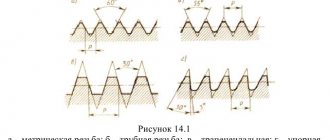
For the thread profile, see Figure 2. Since the diameter of the tapered thread is constantly changing, its size is referred to as a section in the main plane (approximately in the middle of the length of the external thread). In this section, the diameter of the conical thread is equal to the diameter of the cylindrical pipe thread (Figure 14). The position of the main plane is indicated on the working drawing (taken from the standard).
Figure 14. Designation of tapered pipe threads
External thread is designated by the letter R , internal thread - Rc .
The designation of a tapered pipe thread includes the letter R(Rc) and the size in inches without specifying the dimension.
Example: R 1 1/2 LH - outer left, Rс 1/2 - inner.
5.4. Conical inch thread
Gauge for tapered inch threads
Conical inch threads are used in connections of fuel, oil, water, air pipelines of machines and machine tools at low pressures.
The thread profile is shown in Figure 2.
The designation consists of the letter K and the thread size in inches with an indication of the dimension, applied on the shelf of a leader line, as with pipe threads.
Example: K 3/4″ GOST 6111-52.
5.5. Round thread
Round threads are used for mixer valve spindles in accordance with GOST 19681-94 (Sanitary water fittings) and water taps in accordance with GOST 20275-74.
The designation of round threads includes the letters Kr , nominal thread diameter in mm, thread pitch in mm and GOST 13536-68.
Example: Kr 12x2.54 GOST 13536-68, where 2.54 is the thread pitch in mm, 12 is the nominal thread diameter in mm. GOST 13536-68 defines the profile, main dimensions and tolerances of round threads.
Running threads
6.1. Trapezoidal thread
Trapezoidal thread gauges
Used on screws that transmit reciprocating motion and axial force. Threads can be single-start or multi-start .
The thread profile is shown in Figure 2.
The main dimensions, diameters, pitches, tolerances of single-start threads are standardized according to GOST 24737-81, 24738-81, 9562-81.
For multi-start threads, these parameters are found in GOST 24739-81*.
The symbol for a single-start thread consists of the letters Tr , the value of the nominal thread diameter, pitch, and tolerance range.
Example: Tr 40x6-8e - trapezoidal single-start external thread with a diameter of 40 mm with a pitch of 6 mm, Tr 40x6-8e-85 - the same make-up length 85 mm, Tr 40x6LH-7N - the same for the internal left.
to the symbol of a multi-start thread : Tr 20x8(P4)-8e – trapezoidal multi-start external thread with a diameter of 20 mm with a stroke of 8 mm and a pitch of 4 mm.
6.2. Thread persistent
Gauge for thrust threads
It is used on screws subject to unilaterally directed forces, for example in jacks.
Thread profile in Figure 2.
The designation of a thrust thread includes the letter S , nominal diameter in mm, stroke in mm, pitch in mm (for multi-start threads).
Example: S 80x20 – 7h; S 80х20LН – 7h; S 80x20 (P5) – 7h, where 80 is the nominal diameter in mm, 20 is the stroke in mm, 5 is the pitch in mm (for a four-start thread).
A special thread with a standard profile, but a non-standard pitch or diameter, is designated: Sp M40x1.5 - 6g.
Trapezoidal thread
Threaded spiral profiles with trapezoidal contours. They are the most popular shapes used for lead power screws. The main advantages are increased strength and ease of production.
Mostly found in a vice or lead screw of a lathe, as well as in other applications where high load is required. Standard variations include multi-valued, left-handed and self-centering threads, which are less likely to bind under the influence of lateral forces.
The trapezoidal profile provides the highest possible level of bonding. Therefore, it is actively used for coupling structural parts in mechanisms that operate under the strong influence of dynamic loads, for example, in running nuts, which are responsible for fixing rod valves.
About the method of manufacturing a self-locking threaded connection
It is known that existing threads and threaded connections are produced using specially designed and standardized tools. This often requires appropriate equipment and is carried out using existing cutting techniques. But known techniques and methods for producing standardized threads cannot be used for special self-locking threads developed and introduced into production. The problem is that in this case it is cut into a conical shape at the end of the bolt with a special profile. Moreover, the turns have a variable height, but the diameters of the bolt remain constant.
The cross-section of a screw thread has three characteristic parts, that is, a triangle at the apex and two trapezoids in its middle and base. The strength indicators and friction moment in the thread compare favorably with similar parameters of standard threads. A special durable threaded pipe connection has also been developed around the world, which has already received positive reviews. The main result of the invention is a successful solution to the problem by changing the profile.
A self-locking thread lock of a similar prototype consists of a rod and a threaded nut. The threaded end of the bolt also has a conical surface on which the thread is made so that its diameters along the entire length of the thread are also constant. The profile vertices of one component of the threaded connection are made in the form of segments with the same arc radius. The roundings of the depressions of the second connection element are made with the same radius as the tops of the bolt turns. The centers of the arcs of the rod segments are located on a line that is parallel to the generatrix of the cone of the outer surface of the rod. Making the tops of the profile of a nut or bolt shaft in accordance with the given parameters with the specified geometry of the depressions of the rod or nut makes it possible to obtain a strong lock of threaded connections, ensure reliable locking of the nut without the use of additional locking parts, increase the structural and operational characteristics of the connection and reduce its metal consumption.
Thrust thread
This cut, within the framework of the regulatory documents governing its parameters, has the shape of a trapezoid with uneven sides. One of the ridge faces has a slope of 3 degrees, and the other - 30.
Using persistent threads, parts with a diameter from 1 to 60 cm are fastened. The thread pitch ranges from 2 to 25 millimeters. As a rule, this type of thread is used to connect components that are subject to significant axial unidirectional loads during use. The profile features contribute to fairly effective and productive resistance to this type of load.
Gauges for inspection of threaded bolts and nuts
Gauges for monitoring the suitability of cylindrical threaded connections act as a set of rigid means that monitor the suitability of threads. Their advantage is that they provide complete interchangeability of the threads of the twisted parts. All gauges are divided into two main groups: for external and internal threads. According to the principle of construction, they are divided into non-through and through, each of which controls its own tolerance zone, and according to the shape of the surface - into threaded and smooth. Threaded connections with a full bore gauge profile have a nominal profile contour and parameters made with high precision.
Read also: How much oil to fill in a hydraulic jack
Edison carving
The Edison thread profile consists of arcs, the characteristics of which are prescribed in the corresponding GOST. The sides are inclined by 60 degrees, which makes the cutting more resistant to mechanical wear. Therefore, the service life of such connecting parts is quite long.
Therefore, it is quite often used to fasten components of structures where periodic increased loads of a non-permanent nature are observed. For example, it is often used in pipeline fittings.
If you require fasteners of high quality and various types, then the assortment of the First Fasteners store will certainly please you. We have a huge variety of fasteners:
- nuts;
- hairpins;
- nails;
- clamps;
- bolts;
- screws;
- rivets;
- anchors, etc.
Large wholesale orders are delivered throughout Russia. If necessary, a company consultant will answer any questions related to products or store operations. To place a pre-order or clarify any information, call 8-800-201-81-96 or request a call back from a specialist through a special form on the website.
Materials for production
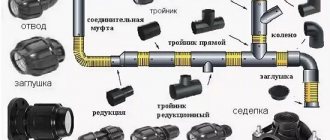
Shaped elements are made from various metal alloys and polymers, but threaded fittings are made only from metal, since plastic threads are easily damaged.
The modern plumbing market offers the following options for threaded type connecting elements:
| Material | Advantages of fittings | Flaws |
| stainless steel | suitable for pipes made of any materials, resistant to corrosion, low temperatures, ultraviolet radiation, as well as water hammer, chemical and mechanical stress, chemically inert and suitable for drinking water pipelines, durable, weigh little; | high cost, sticking during long-term use without prevention; |
| brass with chrome plated, bronze | low cost, ease of dismantling, strength and stability at the level of stainless steel; | cannot be installed on pipelines transporting a working medium with a temperature above 150ºC; without preventive maintenance, the unit weakens, becomes loose, and loses its tightness; |
| copper | resistant to temperature, corrosion and water hammer, do not chemically interact with the working environment; | high cost, not compatible with pipes made of galvanized and chrome-plated non-alloy steel, |
| cast iron | longest service life, low cost; | heavy weight, low corrosion resistance, fouling of reaction products with the working environment and a decrease in the throughput of the unit. |
Basic Power Tool Analysis
Threaded connections account for up to 60-80% of all types of connections that are found in the designs of machines, tractors, cars, and trailers. The labor intensity of unscrewing and tightening screws, bolts, nuts, studs and all other parts with a threaded surface in specialized repair shops is 26-64% of the total labor intensity of disassembly and assembly work, and in service stations this percentage is even higher. This information makes it clear that priority mechanization is necessary when working with threaded parts. During disassembly, a power tool helps preserve a significant amount of fasteners suitable for reuse and reduces the duration of the operation by three to five times. There is an increase in labor productivity by approximately 15%. It is advisable to use a power tool when there is a significant number of fasteners of the same size on the machine, and also when it is not necessary to strictly adhere to the established force. When choosing a power tool for disassembly and assembly work, you need to know in advance the tightening torques of threaded connections. When re-twisting parts, this value must be increased by 10-15%. When unscrewing rusted nuts and screws, the tightening torques of threaded connections must be increased by 1.5-2 times.
Read also: Structure of the rotor of an asynchronous motor
Power tools (nutrunners, stud drivers, etc.) are constantly being modernized. According to the type of engines, it can be electric, hydraulic and pneumatic, and depending on the design - manual, suspended, mobile and stationary.
A threaded connection is the main method of joining two structural elements together. In plumbing and construction practice, threaded connections are used when installing pipelines, shut-off and control valves and connecting consuming equipment to utility systems.
This article presents threaded connections. We will look at their varieties, the components of the fastener, and methods for determining the size and configuration of the thread.