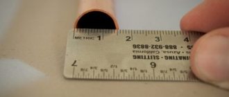
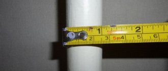
Standards 11383 from '75 and 617 from 2006 are regulatory documents that apply to brass and copper pipes. At the same time, GOST 11383 concerns round drawn thin-walled tubes used in various industries, and 617-2006 concerns round cold-deformed and pressed products for general purposes. The documents establish the requirements, acceptance conditions, assortment, testing methods, control, storage, marking and transportation of pipes.
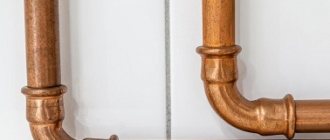
Copper pipes have high strength, ease of installation, and long service life
Application of copper tubes
Copper communications are a fairly common solution for arranging systems for various purposes. Due to their properties, they can be used as a gas pipeline, fuel pipeline, water supply, as well as in heating systems and industry.
Copper products are used as elements of water supply systems for various purposes based on their service life, chemical inertness to substances such as chlorine, bactericidal properties and corrosion resistance. Moreover, installation is possible both for a single consumer and for multi-storey buildings.
Copper tubes are good for heating systems due to their ability to withstand pressure surges and temperatures up to 250 degrees. Such characteristics are explained by the high plasticity of communications. When used in heated floors, copper elements do not wear out.
The use of copper fuel pipelines is possible due to the high tightness of the installed system. The same property makes it possible to install gas pipelines, for example, in apartments.
In addition, copper tubes are included in the designs of various hydraulic and braking systems, heat exchangers, aircraft and trucks, climate control circuits, etc.
Copper pipes are the basis of water supply, heating and other communications, including underground ones
Features of choice for heating
Copper has its own individual characteristics, which impose both operational and technical restrictions on their use. These points must be taken into account when installing the heating system.
Although copper pipes are known for their strength, they can easily withstand pressure surges, temperature changes, and repeated freezing; they do not withstand mechanical stress well. Therefore, when laying a pipeline, protection against impacts should be provided.
A coolant such as water contains sand and other suspended particles. The result of their impact on soft copper is erosion. To avoid this phenomenon, it is necessary to include water purification filters in the system.
The service life of pipes is also affected by water hardness. The value of this indicator in milligrams below 1.42 and above 3.1 significantly reduces their longevity. This is explained by the fact that chlorine dissolved in water reacts with the oxide film present on the walls of the pipe. The result is durable protective armor.
If the water hardness does not meet the standards, this protective layer begins to deteriorate, then due to the presence of chlorine it is regenerated. If this process is repeated many times, copper resources become depleted.
When connecting the pipeline by soldering, overheating, which negatively affects the strength, should be avoided. The flux that remains after soldering must be removed, as it can cause corrosion.
If you need to bend a copper pipe, you need to use a special tool for this. An unsuccessfully bent pipe can be corrected once, and then all that remains is to remove the crumpled section.
The ideal option is to install a heating system from the same pipes. If for some reason this does not work out, you need to use transition fittings - brass or bronze. Adapters made from other materials may not provide electrochemical compatibility.
Copper pipes can be installed even at very low temperatures, so this heating system is a rational solution for regions where cold weather is normal.
To prevent pipes made from other materials from corroding under the influence of copper, a certain sequence of connecting such a combined pipeline relative to the vector of movement of the water flow is needed. Copper pipes must be installed after elements made of other metals.
If you plan to install a heating system with pipes laid inside the wall, you need to use copper pipes in a plastic sheath. It will not only serve as thermal insulation, but will also protect the metal from destruction. Copper pipes and stray currents have a detrimental effect.
Methods of communication production
GOST defines 2 technological operations for producing copper pipes:
- rental;
- pressing (subsequent welding of joints is assumed).
Both methods are suitable for the production of round pipes. Products with a square cross-section are made mainly by pressing. Rolled pipes involve the use of the cold deformation method. Without preheating, ductile metal - copper - can be rolled between two rollers. The workpiece – the sleeve – is simply put on the rolling mill. It is rolled out to the required diameter.
At the final processing stage, communications are divided into unannealed pipes and annealed products. The first type is stronger than heat-treated analogues, since during rolling the material was compacted by deforming the crystal lattice.
Pressed products are made from copper in sheets on special machines. A dimensional blank is cut out of each sheet and fed to the forming press rollers. After giving the required shape, the joining seam is welded.
Note! This process requires the presence of an inert gas environment.
At the last stage, the welded pipe is passed through calibration rollers, which level the profile of the product and also correct longitudinal deformation.
Copper pipes are supplied in coils or straight sections - it depends on their diameter
Do-it-yourself copper pipe soldering technology
Before you start soldering, you need to briefly familiarize yourself with the theory so that the process is easier and clearer. In everyday life, when installing plumbing and heating systems in apartments, soft soldering is used, in which the contact points are heated to 250-300 degrees, which allows the soft solder (tin) to melt. But, despite the apparent ease, such a temperature is dangerous for copper, so everything must be done very carefully and correctly.
Preparation for capillary soldering:
- Cut the pipe to the required size.
- We chamfer the end of the workpiece (this manipulation will reduce the hydraulic resistance at the joint).
- We clean the outer surface of the pipe and the inner surface of the fitting with an abrasive sponge. This will get rid of the oxide film.
- We distribute flux paste over the entire contact area, which will provide soft solder. To make the solder hard, you do not need to use paste.
- With a slight twist, we put the fitting on the pipe until it stops.
- Remove the flux paste from the work surface with a rag.
You can start soldering.
Low temperature soldering of copper pipe:
- We heat the joint until the flux paste begins to melt. To do this, move the burner nozzle smoothly and evenly around the neck.
- After the flux has heated up, apply solder to the entire surface of the connecting seam. We do not touch the solder wire with the burner fire, since the tin needs to melt not from direct contact with the fire, but from the high temperature of the copper product.
- The melting and soldering process is complete. We are waiting for the product to cool completely. The cooling process cannot be accelerated - everything must cool naturally without improvised means.
- At the end of the work, we remove all the flux paste from the part, because it destroys the protective layer of copper products.
Range of thin-walled copper products
Copper tubes according to document 11383-75 must have the dimensions presented in the table.
Table 1
| Diameter, *10 mm | Maximum diameter deviation, *10-1 mm | Linear density (theoretical), g/m, at the wall, *10-2 mm | |||||
| Normal accuracy | Increased accuracy | 15 | 25 | 20 | 30 | 45 | |
| 0,15 | ±1,0 | ±0,5 | 5,659 | — | — | — | — |
| 0,16 | 6,079 | — | 7,823 | — | — | ||
| 0,17 | — | — | 8,384 | — | — | ||
| 0,18 | — | — | — | — | — | ||
| 0,20 | 7,756 | 12,229 | 10,062 | 14,254 | 19,491 | ||
| 0,22 | 8,595 | 13,623 | 11,178 | — | — | ||
| 0,24 | 9,433 | 15,020 | 12,295 | — | — | ||
| 0,25 | — | 15,718 | 12,854 | — | — | ||
| 0,26 | — | 16,700 | 13,412 | — | — | ||
| 0,28 | — | 17,818 | — | — | — | ||
| 0,30 | 11,948 | 19,215 | 15,646 | 22,633 | 32,067 | ||
| 0,32 | — | — | 16,766 | — | — | ||
| 0,34 | — | — | 17,889 | — | — | ||
| 0,35 | — | 22,685 | — | — | — | ||
| 0,36 | — | 23,407 | — | — | — | ||
| 0,38 | — | — | — | — | — | ||
| 0,40 | 16,144 | 26,202 | 21,235 | 31,016 | 44,642 | ||
| 0,45 | — | 29,690 | — | — | — | ||
| 0,48 | — | — | — | 37,724 | — | ||
| 0,50 | 20,333 | 33,188 | 26,825 | 39,400 | 57,218 | ||
| 0,55 | — | — | — | — | — | ||
| 0,60 | 24,526 | 40,175 | 32,414 | 47,784 | 69,794 | ||
| 0,70 | 28,718 | 45,897 | 38,003 | 56,168 | 82,370 | ||
| 0,75 | 30,814 | — | — | — | — | ||
| 0,80 | -1,5 | -1,0 | 32,911 | 54,139 | 43,602 | 64,564 | 94,945 |
| 0,85 | — | — | — | 68,757 | — | ||
| 0,90 | 37,095 | 61,134 | 49,181 | 72,936 | 107,521 | ||
| 0,95 | — | 64,623 | — | — | — | ||
| 1,00 | 41,287 | 68,121 | 54,771 | 81,319 | 120,097 | ||
| 1,02 | — | — | — | — | — | ||
| 1,10 | -2,0 | -1,5 | 45,479 | 75,107 | 60,360 | 89,703 | 132,672 |
| 1,20 | 49,671 | 82,089 | 60,949 | 98,087 | 145,248 | ||
| 1,30 | — | 89,080 | — | 106,471 | 158,180 | ||
| 1,40 | — | — | — | 114,855 | 170,399 | ||
| 1,50 | — | 96,067 | — | 123,238 | 182,975 | ||
| 1,60 | — | — | — | 131,622 | 195,551 | ||
| 1,70 | — | — | — | — | — | ||
| 1,80 | — | — | — | — | — | ||
| 1,90 | -2,4 | -2,0 | — | — | — | — | — |
| 2,00 | — | — | — | — | — | ||
| 2,10 | — | — | — | — | — | ||
| 2,20 | — | — | — | — | — | ||
| 2,40 | — | — | — | — | — | ||
| 2,80 | — | — | — | 232,228 | — | ||
Continuation of Table 1
| Diameter, *10 mm | Maximum diameter deviation, *10-3 mm | Linear density (theoretical), g/m, at the wall, *10-2 mm | ||||||
| Normal accuracy | Increased accuracy | 35 | 50 | 40 | 65 | 70 | 60 | |
| 0,15 | ±100 | ±50 | — | — | — | — | — | — |
| 0,16 | — | — | 13,414 | — | — | — | ||
| 0,17 | — | — | 14,532 | — | — | — | ||
| 0,18 | — | — | — | — | — | — | ||
| 0,20 | 16,136 | 17,889 | — | — | — | |||
| 0,22 | — | — | — | — | — | — | ||
| 0,24 | — | — | — | — | — | — | ||
| 0,25 | 21,031 | 27,946 | 24,175 | — | — | — | ||
| 0,26 | — | 29,343 | 25,362 | — | — | — | ||
| 0,28 | — | — | — | — | — | — | ||
| 0,30 | 25,917 | 34,932 | 29,067 | — | — | 40,242 | ||
| 0,32 | — | — | — | — | — | — | ||
| 0,34 | — | — | — | — | — | 46,956 | ||
| 0,35 | — | — | — | — | — | — | ||
| 0,36 | — | — | — | — | — | — | ||
| 0,38 | — | — | — | — | 60,651 | — | ||
| 0,40 | 35,801 | 48,906 | 40,248 | 60,847 | — | 57,018 | ||
| 0,45 | — | — | — | — | — | — | ||
| 0,48 | — | — | 49,181 | — | — | — | ||
| 0,50 | 45,479 | 62,878 | 51,424 | — | — | 73,777 | ||
| 0,55 | — | — | — | — | — | — | ||
| 0,60 | 55,260 | 76,852 | 63,603 | — | — | 90,545 | ||
| 0,70 | 65,041 | 90,824 | 73,781 | — | — | — | ||
| 0,75 | — | — | — | — | — | — | ||
| 0,80 | -150 | -100 | 74,822 | 104,798 | 84,959 | — | — | 123,079 |
| 0,85 | — | — | — | — | — | — | ||
| 0,90 | 84,603 | 118,770 | 96,138 | — | — | — | ||
| 0,95 | — | — | — | — | — | — | ||
| 1,00 | 94,384 | 132,744 | 107,316 | — | — | 157,615 | ||
| 1,02 | — | — | 109,548 | — | — | — | ||
| 1,10 | -200 | -150 | 104,166 | 146,716 | 118,495 | — | — | — |
| 1,20 | 113,947 | 160,690 | 129,673 | — | — | — | ||
| 1,30 | 123,728 | 174,662 | 140,851 | — | — | — | ||
| 1,40 | 133,509 | 188,636 | 152,030 | — | — | — | ||
| 1,50 | — | 202,608 | 163,208 | — | — | — | ||
| 1,60 | — | 216,582 | 174,587 | — | — | — | ||
| 1,70 | — | 230,554 | — | — | — | — | ||
| 1,80 | — | 244,528 | — | — | — | — | ||
| 1,90 | -240 | -200 | — | 258,501 | — | — | — | — |
| 2,00 | — | 272,474 | — | — | — | — | ||
| 2,10 | — | 286,447 | — | — | — | — | ||
| 2,20 | — | 300,420 | — | — | — | — | ||
| 2,40 | — | 328,366 | — | — | — | — | ||
| 2,80 | — | 284,258 | — | — | — | — | ||
Maximum diameter deviations according to document 617-2006
Copper pipes (GOST 617) can be manufactured with different diameters, lengths and wall thicknesses.
Like other types of pipes, copper products come in different diameters and with different wall thicknesses
The permissible nominal outer size of a cold-deformed pipe and its maximum deviations are given in the table.
table 2
| Outer diameter, *103 mm | Maximum deviation, *10-2 mm |
| 0,003 – 0,01 | — 15 |
| 0,01 – 0,018 | — 20 |
| 0,018 – 0,03 | — 24 |
| 0,03 – 0,048 | — 30 |
| 0,048 – 0,076 | — 40 |
| 0,076 – 0,1 | — 50 |
| 0,1 – 0,12 | ± 30 |
| 0,12 – 0,139 | ± 40 |
| 0,139 – 0,17 | ± 50 |
| 0,17 – 0,235 | ± 70 |
| 0,235 – 0,36 | ± 90 |
Having agreed with the consumer, it is possible to manufacture a pipe (cold-deformed) with a deviation in the average diametrical size. The corresponding values according to GOST 617 are given in the table.
Table 3
| Outer diameter, *103 mm | Pipe ovality, *10-2 mm | Diameter deviation, *10-1 mm |
| 0,003 – 0,01 | 12 | ±0,6 |
| 0,01 – 0,02 | 16 | ±0,8 |
| 0,02 – 0,03 | 24 | ±1,2 |
| 0,03 – 0,05 | 30 | ±1,5 |
| 0,05 – 0,10 | 50 | ±2,0 |
| 0,10 – 0,20 | 100 | ±5,0 |
| 0,20 – 0,30 | 150 | ±7,5 |
| 0,30 – 0,36 | 200 | ±10 |
Pressed pipes should not exceed the maximum diameter deviations (according to GOST 617) given in the table.
Table 4
| Outer diameter, *103 mm | Deviation, *10-1 mm |
| 0,03-0,036 | ±3,5 |
| 0,036-0,045 | ±4 |
| 0,045-0,050 | ±5 |
| 0,050-0,060 | ±6 |
| 0,060-0,070 | ±7 |
| 0,070-0,080 | ±8 |
| 0,080-0,090 | ±9 |
| 0,090-0,105 | ±10 |
| 0,105-0,110 | ±11 |
| 0,110-0,120 | ±12 |
| 0,120-0,130 | ±13 |
| 0,130-0,140 | ±14 |
| 0,140-0,150 | ±15 |
| 0,150-0,160 | ±16 |
| 0,160-0,170 | ±17 |
| 0,170-0,180 | ±18 |
| 0,180-0,190 | ±19 |
| 0,190-0,200 | ±20 |
| 0,200-0,220 | ±22 |
| 0,220-0,250 | ±25 |
| 0,250-0,280 | ±28 |
Acceptable dimensions of thin-walled pipes
Standard 11383 defines the permissible deviations in wall thickness (thin-walled drawn pipes) depending on the accuracy of manufacture. The corresponding values are given in the table.
Table 5
| Wall, *10-3 mm | Deviation, *10-3 mm | |
| Increased accuracy | Normal accuracy | |
| 150 | ±20 | ±30 |
| 200 | ||
| 250 | ±30 | ±40 |
| 300 | ||
| 350 | ||
| 400 | ±40 | ±50 |
| 450 | ||
| 500 | ±50 | ±60 |
| 600 | ±60 | ±80 |
| 650 | ±80 | ±100 |
| 700 | ||
Thin-walled tubes (standard 11383-75) can be produced in lengths from one to three meters. It is possible to have products from half a meter to 1 meter, but their quantity should not exceed 10% of the mass of the entire batch.
The sections in which copper pipes are produced have length restrictions
If the outer diameter is less than 1 centimeter, then production in coils is acceptable. The limit on their length is 10 meters. The upper limit for the length of a pipe section of more than 3 meters is 4.5 m. Deviation in the length of the measured product is up to +10 mm.
Document 11383-75 also defines the curvature of solid tubes. The required values are given in the table.
Table 6
| Wall, *10-1 mm | Diameter, *10-1 mm | Curvature value per 1 m, mm, no more |
| 1,5-2,5 | 15-60 | 5 |
| More than 3.0 | 15-60 | 8 |
| All sizes | More than 60 | 10 |
In accordance with consumer requirements, the curvature of the tubes can be less than 3 millimeters.
Advantages of copper pipelines
All the advantages of copper pipes stem from the unique properties of this material, products from which:
- They are harmless and have bactericidal properties.
- They do not age for a long time and do not lose their performance characteristics.
- Resistant to corrosion and ultraviolet radiation. They operate in a wide temperature range - from -200 to +350⁰С.
- Immune to the effects of chlorine in tap water.
- They have high thermal conductivity, which increases the efficiency of the heating system.
- Plaque does not form on the surface of copper pipes with a low roughness coefficient.
- Freeze resistant. The pipeline does not collapse and does not lose its original characteristics, subjected to freezing up to four times.
- Capable of maintaining strength properties under pressure reaching 200 – 400 atmospheres.
- Vibration resistant.
- They have a wide range of products.
- 100% recyclable.
Many people are often stopped from choosing copper pipes for heating by both the high price of the pipeline itself and the consumables.
A heating device made from copper pipes is accompanied by the purchase of a variety of fasteners, connectors, and fittings. The cost of all this is about 30% of the amount spent on pipes
Copper pipes are lightweight and can be cut, bent and soldered. The most popular method of connecting copper pipelines is soldering at high temperatures using silver-bronze solder. Faster installation is carried out using fittings.
Maximum deviations of wall thicknesses
GOST 617 defines wall thicknesses and their deviations for a cold-deformed tube. The corresponding values are given in the table.
Table 7
| Wall thickness, *10-1 mm | Nominal outer size, *10-1 mm | Maximum deviation, *10-2 mm | |
| Normal accuracy | Increased accuracy | ||
| 8 | 30-160 | ±8 | ±7 |
| 10 | 40-600 | ±10 | ±9 |
| 12 | 50-420 | ±12 | ±11 |
| 15 | 60-1000 | ±15 | ±13 |
| 20 | 60-1000 | ±20 | ±18 |
| 25 | 90-1650 | ±25 | ±20 |
| 30 | 110-2310 | ±25 | ±24 |
| 35 | 150-3570 | ±30 | ±25 |
| 40 | 160-3580 | ±30 | ±28 |
| 45 | 230-900 | ±35 | ±32 |
| 50 | 200-3600 | ±40 | ±35 |
| 60 | 220-2120 | ±50 | ±42 |
| 70 | 240-3500 | ±60 | ±49 |
| 80 | 800-3500 | ±60 | ±56 |
| 100 | 340-3150 | ±75 | — |
It is permissible to produce copper tubes with intermediate wall thicknesses. In this case, the maximum deviations are selected based on the closest value.
Note! By agreement with the consumer, it is possible to produce copper products for which deviations are expressed as a percentage of the total thickness.
The thickness of the pipe wall is also regulated by GOST, but by agreement with the customer, products of non-standard sizes can also be produced
For cold-deformed pipes, the corresponding parameters according to GOST 617 are given in the table.
Table 8
| External size, *10-1 mm | Deviation, *10-1, % | |||
| from the wall 0.8-1 mm | from the wall 1-3 mm | from the wall 3-6 mm | from the wall 6-10 mm | |
| 30-400 | ±150 | ±130 | ±110 | ±100 |
| 400-1200 | ±150 | ±130 | ±120 | ±110 |
| 1200-2500 | — | ±130 | ±130 | ±120 |
| 2500-3600 | — | — | ±150 | ±150 |
According to GOST, pressed copper pipes must have walls with maximum deviations indicated in the table.
Table 9
| Wall, *10-1 mm | Outer diameter, mm | Wall thickness deviation, *10-1 mm |
| 50 | 30-70 | ±5 |
| 60 | From 32 to 42 | ±6 |
| 70 | From 36 to 44 | ±7 |
| 75 | 40-90 | ±7,5 |
| 80 | From 42 to 46 | ±8 |
| 85 | 40 | ±8,5 |
| 100 | 34-280 | ±10 |
| 125 | 50-195 | ±12 |
| 150 | 50-270 | ±14 |
| 175 | 75-195 | ±16 |
| 200 | 80-280 | ±18 |
| 225 | 85-195 | ±18 |
| 250 | 90-270 | ±20 |
| 275 | 95-195 | ±22 |
| 300 | 100-280 | ±24 |
Standardization of copper pipe length
GOST 617-2006 standardizes the lengths of copper pipes. Products can be produced in coils or lengths. In the second case, it is allowed to manufacture pipes of unmeasured, as well as measured (or multiple measured) lengths. Thus, the length of cold-deformed products can be in the range of 15-60 (*10-1 m), pressed ones - 10-60 (*10-1 m).
Coils with pipes can be either free or ordered winding
For pipes of a length that is a multiple of the measured length, it is necessary to allow half a centimeter for each cut, and deviations of the total length are set as for products of a measured length.
Pipes in coils are supplied with a length of at least 10 meters with an outer diameter of up to 1.8 cm. Upon agreement with the consumer, drawn products can be manufactured in coils of the following types:
- BT – free winding coil.
- BU – coil of ordered layer-by-layer winding.
- BS – coil of spiral flat winding.
For products of measured length, maximum deviations must correspond to the values in the table.
Table 10
| Diameter, *10-1 mm | Length deviation, *10-1 mm | |
| <2000 | ≥2000 | |
| 30-500 | +60 | +100 |
| 500-1500 | +100 | +150 |
| >1500 | +180 | +240 |
Similar parameters, if there is increased manufacturing accuracy, are given in the table.
Table 11
| Diameter, *10-1 mm | Length deviation, *10 mm | |
| 1000-4000 | >4000 | |
| 30-250 | +0,5 | Values are agreed with the consumer |
| 250-1000 | +0,7 | |
| >1000 | +1,0 | |
Symbol for copper tubes
GOSTs 617-2006 and 11383-75 establish a general scheme for the symbols of products. Its composition, broken down by document, is given in the table.
Table 12
| Parameter | According to 617-2006 | According to 11383-75 |
| Preparation method | G – pressed D – cold-deformed (cold-rolled or drawn) | D – pulled |
| Section shape | KR - round | |
| Precision manufacturing | I – normal (along the wall) and increased (along the diameter) N – normal (in diameter and wall) P – increased (in diameter and wall) K – increased (along the wall) and normal in diameter Y – in % of wall thickness C – normal (based on the average diameter) | N – normal and P – increased |
| State | M – soft L – soft with increased plasticity P – semi-solid F – semi-solid with increased strength T – hard H – hard with increased strength | M – soft T – hard |
| Dimensions | Diameter and wall | |
| Length | ND – undimensional CD – multiple of dimensional | CD – multiple ND - unmeasured MD – measured BT – in bays |
| Metal grade | — | |
| Special conditions | B – pipes with increased length accuracy O – pipes with increased length accuracy P – regulated requirements regarding tensile tests H - regulated requirements regarding Vickers hardness measurements | L – increased plasticity G – pressed blank C – welded workpiece P – any workpiece |
| Standard designation | Name GOST | |
Some characteristics of copper tubes
Unlike steel pipes, copper pipes are not afraid of water freezing inside the system. Thanks to their plasticity, they can expand. After defrosting, the walls of the products do not crack and are able to function effectively again.
Copper pipes are able to withstand high pressure, high temperature and do not fail when these indicators change
The roughness of a copper tube is 100 times lower than that of steel, and 5 times lower than that of plastic. Thus, high pipeline capacity is ensured when using communications of smaller diameters.
Note! If the temperature of the liquid medium is 100 ºС, then the copper water supply can withstand a pressure of 2.2-23 (*10) atmospheres.
The use of a copper pipe in the shell will protect the network from the influence of stray currents and also reduce heat loss. Thanks to the protective coating, it is impossible for condensation to form on the product. The insulation can be a polyethylene layer, a polyurethane foam coating and other polymer forms.
physical characteristics
There is a large selection of different soft copper pipes on sale. They are supplied in coils. Their key parameter is diameter. Its size directly affects the rate of refrigerant circulation in the pipeline. Correct selection of structures by diameter will reduce the amount of pressure loss in the air conditioning system.
The market offers copper pipe products with a cross-section from six to one hundred millimeters. To arrange the air conditioner route, as a rule, the following options are used:
| Diameters in millimeters | In inches |
| 6.35 | 1/4 |
| 9.52 | 3/8 |
| 12.70 | 1/2 |
| 15.88 | 5/8 |
| 19.05 | 3/4 |
To choose the right product by diameter, you need to take into account the power of the air conditioner. The volume of refrigerant passing through the line directly depends on it. The greater the power of the unit, the greater the amount of coolant in the system. In order for such a system to function efficiently, it is necessary to use products of a larger cross-section for arranging the pipeline.
The minimum thickness of copper tube for air conditioners is 0.7 mm. The length of the structures varies. For products from the most popular manufacturers, the pipe size does not exceed two meters. They are sold in coils up to fifty meters long. Each two-meter section is equipped with special plastic plugs. They are inserted into both ends of the tube, providing protection against dirt and moisture.
Chemical composition of copper for pipes according to GOST 617
GOST 617 determines the content of impurities in copper for the manufacture of pipes for the following grades: M3r, M1, M1f, M2, M1r, M3 and M2r.
Table 13
| Element | Mass fraction of component for brands, *10-3% | ||||||
| M1 | M3 | M1r | M2 | M1f | M3r | M2r | |
| Copper and silver | 99,9 | 99,5 | 99,9 | 99,7 | 99,9 | 99,5 | 99,7 |
| Bismuth | 1 | 3 | 10 | 2 | 10 | 3 | 2 |
| Iron | 5 | 50 | 50 | 50 | 50 | 20 | 50 |
| Nickel | 2 | 200 | 20 | 200 | 20 | 200 | 200 |
| Zinc | 4 | — | 50 | — | 50 | — | — |
| Tin | 2 | 50 | 20 | 50 | 20 | 50 | 50 |
| Antimony | 2 | 10 | 20 | 5 | 20 | 50 | 5 |
| Arsenic | 2 | 50 | 20 | 10 | 20 | 50 | 10 |
| Lead | 5 | 50 | 50 | 10 | 50 | 30 | 10 |
| Sulfur | 4 | 10 | 50 | 10 | 50 | 10 | 10 |
| Oxygen | 50 | 80 | 100 | 70 | — | 10 | 10 |
| Phosphorus | — | — | From 2 to 12 | — | From 12 to 40 | From 5 to 60 | From 5 to 60 |
Basic mechanical properties of products
Regulatory documents for copper products determine the mechanical properties that the finished product must have.
For high-strength pipes, GOST specifies the mechanical properties that they must have
The corresponding indicators according to GOST 617 are given in the table (symbols: P - tensile, P - determination of strength, linear dimensions in millimeters).
Table 14
| Cold- deformed pipes | Pressed pipes | |||||||||
| Material condition | Soft | Semi- hard | Solid | — | ||||||
| Type of test | R | P | R | R | P | R | P | R | ||
| Diameter | Min., *10-1 | 30 | 100 | 30 | 30 | 100 | — | — | 2000 | |
| Max. | 360 | 360 | 360 | 360 | 360 | 200 | 200 | — | ||
| Wall | Min., *10-1 | 8 | 10 | 8 | 8 | 10 | 50 | 50 | 50 | |
| Max. | 10 | 10 | 10 | 10 | 10 | 30 | 30 | 30 | ||
| Tensile strength, *103 kPa | Min. | 200 | — | 240 | 280 | — | 190 | — | 180 | |
| After rupture, relative elongation, % | Min. | On short samples | 38 | — | 10 | — | — | 32 | — | 32 |
| Min. | On long samples | 35 | — | 8 | — | — | 30 | — | 30 | |
| Vickers hardness | Min. | — | — | — | — | 90 | — | — | — | |
| Max. | — | 55 | — | — | 135 | — | 80 | — | ||
Having agreed with the consumer, it is possible to produce soft pipes with increased ductility, and hard and semi-hard pipes with increased strength.
For such cold-formed products, the mechanical properties must correspond to the table.
Table 15
| Material condition | Test type | Tensile strength, *10, MPa | After rupture, relative elongation, % |
| Min. | Min. | ||
| Soft | Tensile | 21,0 | 40 |
| Semi-solid | 27,0 | 8 | |
| Solid | 31,0 | — |
Pipe surface requirements
GOST 617, like document 11383-75, defines the basic requirements for the surface of products. There should be no contamination inside or outside the pipe that would make inspection difficult.
Note! According to standard 11383-75, the presence of shells, cracks or delaminations on the surface of the finished product is strictly unacceptable.
Individual minor surface defects are possible, dents of no more than a quarter of a millimeter, the number of which is not more than 2 per meter of length, if they do not take the overall dimensions beyond the maximum deviation values (GOST 11383 from ’75). At the same time, no more than 10% of products with such defects are allowed in a batch.
If solid copper tubes (document 11383) are manufactured with increased precision, then local dents can have a depth of no more than 0.2 mm and the number of such products cannot exceed 2% of the entire batch. It is acceptable to have ringing, tarnish, oxidation, and local darkening, which do not impede visual inspection.
When checking the quality of pipes, not only their mechanical properties are assessed, but also their appearance.
Advantages
Advantages:
- They can easily withstand heating of several hundred degrees (only at a temperature of 6000 degrees does “annealing” occur, and the pipe begins to lose its strength, acquiring plasticity).
- Capable of withstanding pressure up to 30 atmospheres or more.
- Due to their plasticity, they do not collapse if the water freezes inside.
- Copper has anti-corrosion properties and also does not react to ultraviolet radiation and active chemicals, which increases the service life of the pipe to 50 years or more.
- Do not allow diffusion of air into the coolant through the walls.
- Copper can easily be used at the outlet of a heat generator, because, compared to polymers, it has a low coefficient of thermal expansion (maximum 1.5 mm per linear meter at 900 degrees).
- The internal surface has less roughness compared to steel (but not polymer), which significantly reduces the hydraulic resistance in the system, so less powerful pumps can be used. Due to the absence of roughness, unnecessary deposits do not accumulate inside the pipe.
- Due to the thin walls and fittings, the flow area at the joints remains unchanged, so the hydraulic characteristics of the pipeline do not deteriorate. The entire system is light and compact. Only the outer diameter of the internal section is much larger than that of steel or polymer.
- Copper is safe for humans. It has mild antibacterial properties.
- This is a beautiful material that will not spoil the appearance of the room.
Bevel cut and ovality according to GOST standards
Thin-walled copper tubes (11383-75) must be cut straight and free of burrs. The standard regulates the cutting angle, which for products with a diameter of up to one centimeter is no more than one millimeter, and for large pipes - two millimeters. If the products are supplied in coils, then there are no restrictions on this parameter.
The unevenness of wall thicknesses should not exceed the maximum deviations (GOST 11383). If this value is less than 1/20 of the outer diameter, the required ovality is less than 0.5 mm (for high-precision products - 0.25 mm). By agreement with consumers, this figure can be increased.
GOST 617 determines the cut bevel values, which are presented in the table.
Table 17
| Diameter, *104 mm | Kosina, no more, mm |
| up to 0.002 | 2 |
| 0,002-0,005 | 3 |
| 0,005-0,01 | 4 |
| 0,01-0,017 | 5 |
| more than 0.017 | 7 |
This standard does not specify ovality:
- for pipes in coils;
- pressed with a wall less than 1/15 of the outer size;
- cold-deformed in solid and semi-solid states with a wall less than 1/30 of the external size;
- cold-formed products in a soft state.
GOST 617 also allows for the production of pipes in coils with the ends cut off.
Fittings for connecting copper pipelines
Copper fittings are shaped elements by means of which individual sections of the pipeline are joined together. Copper pipe fittings are available in the following configurations:
- parallel couplings;
- tees;
- squares (45 and 90 degrees);
- crosses.
Types of copper fittings
The above copper fittings can be one-size - for connecting pipes of the same diameter, or transitional - for connecting sections of pipelines of different sizes.
Solder fittings
Connecting products intended for joining by soldering are called capillary. Their inner walls are covered with a thin layer of tin solder - the molten solder fills the gap between the walls of the connecting products and, after hardening, firmly adheres them to each other.
Among the high-quality products for soldering, we note Sanha fittings. This company produces copper fittings of all common sizes according to German quality standards from CW024A alloy. The connections are able to withstand pressure in the range of 16-40 Bar and an operating temperature of 110 degrees.
The technology for connecting copper pipelines using the soldering method is quite simple to implement:
- The mating surfaces of the pipe and fittings are cleaned of dirt, degreased and treated with fine-grained sandpaper.
- A layer of low-temperature flux up to 1 mm thick is applied to the pipe walls.
- The connecting elements are joined together, after which the joint is heated with a hot air gun or gas burner to a temperature of 4000 for 10-15 seconds .
- Wait for the joint to cool down, after which the remaining flux is cleaned with a rag.
Scheme for soldering copper pipes
Soldering must be done in a ventilated area, since when solder and flux melt, gases harmful to the body are released.
Push-in connections
Collet fittings, also known as compression fittings for copper pipes, make a serviceable connection that must be dismantled. All collet fittings are classified into two groups:
- “A” – for products made of hard and semi-hard copper;
- “B” – for pipes made of soft copper.
They differ in that class “B” fittings have an internal sleeve - a fitting, onto which the connected sections of the pipeline are mounted. The fitting acts as a supporting element that prevents deformation of the copper walls during crimping.
Compression Copper Fitting
Connection installation technology:
- A union nut and a split ring are put on the pipe.
- The ring is placed at a distance of 1 cm from the cut.
- The pipe is pressed onto the fitting fitting.
- The union nut is tightened by hand until it stops, after which it is tightened using an adjustable or open-end wrench.
Press connection
Press fittings for copper pipes consist of a body, a fitting and a crimp sleeve. Their installation takes a minimum of time - the joining sections of the pipeline are inserted into the socket on the fitting, after which the sleeve is crimped using press pliers. This tool can be rented at a plumbing store or purchased, prices start at 3 thousand rubles.
Press fitting installation
This connection is maintenance-free; unlike a collet joint, you will not be able to dismantle it without compromising the integrity of the fitting. In case of leaks, it is necessary to replace the connecting element. Note that press fittings are the most reliable and durable, their service life reaches up to 30 years.
Acceptance of pipes according to document 11383-75
According to GOST, products are accepted in batches. Each of them should not exceed 500 kg in weight.
Pipes can be supplied in small quantities, which include one product size
A batch may include tubes of the same size, brand of alloy or metal, material condition and manufacturing accuracy. The accompanying document shall indicate:
- size;
- trademark;
- grade of alloy or metal;
- manufacturing method used;
- condition of the material;
- number of the corresponding batch;
- net weight of the batch;
- standard.
At the request of the consumer, the accompanying quality document may also contain test results. Checking the outer surface is carried out for each pipe of the batch, the inner surface is checked for 3 products with a diameter greater than 3 mm, from every hundred kilograms. If the internal size is less than 3 mm, then such a check is not performed.
Note! Tests for tightness and flattening of tubes from welded blanks are carried out on 3 products per batch. 2 tubes per batch are subject to chemical analysis.
If the results obtained are unsatisfactory for at least 1 of the required indicators, then repeated tests are necessary. They should be carried out on twice as many samples taken from the same batch. The results of repeated checks apply to the entire tested lot.
Applicable test methods
When inspecting the surface from the outside, magnifying devices are not used. If the tubes are made without ringing, then control is carried out by comparison with reference samples that are agreed upon with the consumer. Inspection of the surface of products with a diameter of more than 2 cm in the middle is created on light screens.
The outer diameter is measured with a micrometer, the division value of which is 1/100 mm (GOST 6507) or another device that can provide the specified accuracy. To control the thickness of the wall (for products with a diameter of less than 30 * 10 -1 mm), weighing is used. The mass of a meter of pipe is found by weighing five 20 cm pieces, which are taken from every hundred kilograms of the batch.
The curvature of the samples is determined by placing them on a slab and applying a 1 meter long steel ruler. Using templates and probes, the longest distance from the ruler to the pipe is measured.
Tests for tension are carried out on long products in accordance with GOST 10006, for flattening - in accordance with GOST 8695. Preparation and sampling for chemical studies must comply with GOST 24231.
The tightness of the products is tested with air at a pressure of 690 kPa for five seconds in a bathtub filled with water. In this case, there should be no leakage from the pipe. It is also possible, after agreeing with the consumer on the methodology, to perform similar checks using non-destructive methods.
Technical documents 11383 and 617 regulate all the necessary criteria and characteristics that copper tubes must have. The quality and effectiveness of the use of such communications in many systems determine the enormous distribution and demand for such products.
Posted in Do it yourselfTagged gost, copper, assortment, table Table, pipe
