Connecting gas to a private home is not an accessible procedure for everyone, but thanks to the inexpensive cost of natural fuel, it will pay for itself in the coming years. Almost all work, with the exception of excavation and some installation work, is carried out by gas service employees according to a predetermined price list.
To save money, homeowners take on some of the work themselves - for example, digging a trench from the highway to the house. They can also take part in a process such as laying a gas pipeline in a case through a wall. If you figure it out, you can handle this procedure yourself, while representatives of Regional Gas Agency charge 8-10 thousand rubles for this.
For those who decided to arrange the gas pipe entry into the house with their own hands, we have collected all the information about lining in one place. You will learn everything from the regulatory framework to practical advice from our article. Our advice will be useful to independent owners of country property.
What does a gas pipeline need a case for?
In the installation of underground gas communications, as a rule, steel or polyethylene gas pipes are used that can withstand the pressure of the medium passing through them. Their strength characteristics are designed for loads created by soil thicknesses up to 2.0-2.2 m. However, standard rolled pipes are not designed for possible transport loads from above, i.e. over the gas main.
It is also not taken into account that it is undesirable for the pipelines through which gas moves to the consumer to pass under other communication lines. There are also geological and hydrogeological restrictions, according to which the gas pipeline has to be laid above the established standards.
If it is impossible to find a laying route that does not cross other engineering structures, in accordance with the requirements of SNiP 42-01-2002, it is necessary to ensure a safe vertical distance between pipelines. This is 0.2 or more meters, which as a result changes the depth of the gas pipeline.
In difficult sections of the gas pipeline route that require protection of the pipe from damage, installation is carried out in cases
The laying depth of the gas pipe is also changed if rock formations or unstable groundwater levels interfere with laying it at the standard depth mark.
How to protect a gas pipeline if additional load on the line is inevitable? In all of these cases, cases are used, which are a rigid round or semicircular casing made of steel alloy, polyethylene or fiberglass. It is this that protects the path of blue fuel from possible damage.
Note that when installing gas pipeline protection, it is even more difficult to monitor the condition of the pipe laid in the casing. To facilitate the difficult work of linemen, mining industry employees and gas supply structures, a control tube is installed on the gas pipeline.
We list all the possible prerequisites for installing cases with control devices over gas pipelines:
- The location of the underground gas main is close to a residential building or public building.
- Laying a gas pipeline at shallow depths.
- Installation under transport routes: automobile, tram, railway tracks.
- The presence of a threaded connection or weld on electric-welded metal pipes and polyethylene analogues.
- "Intersection", i.e. passage 0.2 m above or below the heating network and other communication lines.
- Inserting the gas supply pipe into the house through a load-bearing wall and vertical intersection of the floors.
- Construction of a control and measuring point with a protective carpet. They are installed along the entire route every 200 m within cities and other populated areas. In areas free of habitation, they are installed every 500 m.
All of the listed options, except for crossing the floors with a gas pipe, as well as arranging the entrance and exit of the underground line to the surface, provide for the installation of a control tube on one of the edges of the case.
Even in the case of installation over a problematic weld, it is permissible to use not cases as a base for attaching the tube, but a semicircular metal casing.
Steel, polyethylene and fiberglass casings are used in the construction of underground gas pipelines. Structurally, they are solid pipes, connected by two halves of a pipe or one semicircular casing
The control tube is placed in a place convenient for monitoring. Those. from the side from which the gas worker’s approach to carry out monitoring operations is possible, safe and does not require permits.
If two gas pipelines are laid in one trench, which is allowed by building regulations, then the location of the cases with the pipes connected to them should ensure tracking of both systems.
A control tube is installed on each case designed to protect the gas pipeline, which is necessary to monitor the technical condition of the underground system and determine the moment of pressure drop
The cases are installed both on newly laid gas pipeline lines and on existing branches by piercing or pushing through the soil. They should extend beyond the boundaries of highways, highways, load-bearing walls and other structures by 2 m on both edges.
Control tube
The control tubes are lowered with their free end into the tank to different depths and end at levels corresponding to the controlled volumes. Shut-off needle valves are screwed onto the outer ends of the tubes, the opening of which determines from the exiting gas stream whether it is gas or liquid. To reduce the risk of being struck by a gas stream, a throttle with a diameter of 3 mm is installed in front of the valve. When opening valves to check the level of liquefied gas, operating personnel must always wear gloves on their hands and stand to the side of the valve outlet fitting to prevent the escaping gas stream from hitting the operator, especially exposed, unprotected parts of his body. In cases where the evaporation capacity of the tanks is insufficient to supply gas to consumers, piping the tanks with evaporation units is used.
| Relief safety valve. |
The control tubes are lowered with their free end into the tank to various depths to the levels of the controlled media.
Control tubes are more effective on a gas pipeline that is located above the groundwater level. In some cases, devices are installed that block the gas from leaking into the danger zone and make it easier to detect. A loosened strip of earth allows gas to escape as it spreads from the leak point towards basements and buildings. To control leaks and remove gas in the desired direction, in some cases permanently open drains, similar to control tubes, are installed.
The control tube is a U-shaped tube filled with soda lime and calcium chloride in approximately equal quantities. The layers of calcium chloride and soda lime should be separated at the bottom with a small piece of cotton wool (Fig. 45), and at the top they should not reach 6 mm to the side outlet tubes; they are covered with pieces of cotton wool on top; The tube is closed with stoppers and filled with Mendeleev's putty. Rubber tubes covered with scraps of glass rods are also placed on the side tubes.
| Main characteristics of safety relief valves. |
The control tube (Fig. VI-33) is made of a steel pipe with a diameter of 2, the lower end of which is welded to a casing made of sheet steel 2 - 3 mm thick and 350 mm wide, bent in the form of a semicircle and usually placed above the joint of the gas pipeline. The space between the casing and the gas pipeline is filled with a layer of crushed stone or gravel. The upper end of the control tube is equipped with a stopper, brought to the surface of the earth and protected by KB-ver.
| Control tube device. |
Inspection tubes are of great importance for correct operational supervision; They are the main device that makes it possible to check the density of a gas pipeline from the surface of the earth.
Control tubes can only conditionally be classified as devices that protect underground gas networks from damage. Their main task is not to protect, but to create conditions that allow timely detection of a gas leak from a pipe, take urgent measures to protect the gas pipeline from further damage, as well as eliminate possible consequences of the leak.
Control tubes are installed along the gas pipeline route at certain distances, as well as above points in the gas pipeline for which it is desirable to carry out systematic operational supervision.
| Control device Installation for suction and tubing of gas from the ground. |
Inspection tubes are of great importance for correct operational supervision; They are the main device that makes it possible to check the density of a gas pipeline from the surface of the earth.
Control tubes are brought to the surface of the earth under the carpet in accordance with the requirements of 2 - 1 - 5 of these Rules.
| Reservoir head. |
Example of practical implementation
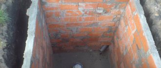
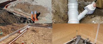
The gas line runs near a residential building, just 10 meters from the fence. When collecting documents, it turned out that the soil is ideal for laying the pipe and no additional measures are required to strengthen the pipeline
The house is located on a plot with a vegetable garden and trees, so when digging a trench we had to “loop” between pine and apple trees.
In total, the distance from the tie-in to the central highway to the basement input is 70 m. The depth of the trench is 1 m, width is 35-40 cm. This is enough to lay a pipe, and in case of repair, carry out replacement measures.
Next, the main line runs along the wall and is divided into two branches, one of which goes to the gas stove, the second to the household heating boiler.
There is an article on our website where we examined in detail the process of gasification of a private home. Recommended reading.
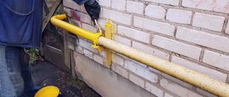
Passage of a flue through the wall of a building
The most successful way to exit the gas duct in the partition is from the pediment side. But if this cannot be done and the chimney comes out from the side of the slope, then we weld the stand and attach the structure to it with sliding fasteners. The result is an intelligent and long-lived system.
Diagram of the chimney exit through the wall and one of the implementation options
Laying gas pipelines indoors
In this case, certain safety standards must also be observed. The transit gas pipeline is laid inside buildings along the external surfaces of the walls at a height of at least 1.5 meters from the floor. Sometimes pipes are pulled in channels covered with shields. The latter, according to regulations, must be easily removable. Gas pipelines are laid through walls or ceilings in metal sleeves insulated with non-flammable material.
According to the regulations, it is prohibited to pull pipes:
- on door and window frames;
- transoms;
- platbands
Before installing gas equipment next to them, wooden walls must be insulated with asbestos cement sheets. All joints of the internal gas pipeline are connected by welding. Detachable connections can only be made in places where shut-off valves are installed.
Steel pipes are usually used to assemble internal systems. But sometimes copper ones are also used for this purpose. It is not allowed to use such highways only for transporting LPG.
The connection of the internal transit gas pipeline to the external one and its assembly must, according to the standards, be carried out only by specialists from a licensed company. After installation of the system, it is tested and accepted with the signing of the corresponding document.
Types of gas pipelines
Depending on the pressure under which gas moves through the pipes, gas pipelines are classified into three main types:
- low pressure lines;
- medium pressure lines;
- high pressure lines.
Low pressure line. The pressure indicator in such communications reaches 0.05 kgf/cm². Such pressure in gas pipeline structures is typical for economic systems that supply gas to ordinary consumers. Such networks are installed for residential and administrative buildings, which include: multi-storey residential buildings, educational institutions, offices, hospitals, etc.
Pipelines with average pressure indicators. In such pipelines, gas is transported under pressure from 0.05 kgf/cm² to 3.0 kgf/cm². Such lines are in most cases used as main lines, and are also installed in the main city boiler houses.
High pressure gas pipelines. The pressure indicator in such pipelines can vary from 3.0 kgf/cm² to 6.0 kgf/cm². Such lines are installed to supply gas to various production enterprises.
Networks transporting gas to end consumers are low pressure lines
There are situations in which the pressure in a gas pipeline structure may exceed the established limits. In some cases it reaches 12.0 kgf/cm² (highest pressure line). Organizing a system with such pressure indicators requires separate calculations. All gas pipelines are classified not only by pressure, but also depending on the material from which they are made.
What pipes can be used?
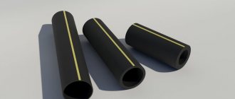
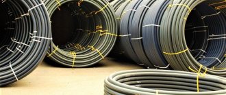
Modern gas pipelines can be made from various materials, but only two of them are in demand: steel and polyethylene. Moreover, the repeatedly mentioned joint venture recommends giving preference to pipes made from the latest type of material.
The photo shows steel pipes. Until recently, they were the most popular, but today they are being actively replaced by more effective, reliable and safe polyethylene analogues
The reason for the demand for polyethylene pipes is that they are not susceptible to stray currents and are more resistant to corrosion. Due to this, they retain their performance characteristics throughout their entire service life.
The listed features are important - they reduce operating costs and make the gas pipeline safer.
Protection of steel pipes from corrosion. All of these layers significantly extend the service life, but make the gasket more expensive and labor-intensive. Especially in comparison with polymer pipe products
For comparison, steel pipes, according to the requirements of the profile joint venture, must be protected from:
- underground (ground, soil) corrosion - this provision is relevant for all underground gas pipelines;
- corrosion caused by so-called stray currents - this rule applies to underground gas pipelines;
- atmospheric corrosion - the requirement applies to above-ground gas pipelines.
Protection of pipes and other elements made of steel is a mandatory procedure.
This is stated in SP 62.13330.2011, which refers to:
- GOST 9.602-2005, which sets out the requirements for combating corrosion in the case of underground gas pipelines.
- SNiP 2.03.11-85 - this document specifies the rules for the protection of above-ground steel pipelines.
Each of the listed documents repeats the requirement that measures to prevent corrosion are mandatory.
Polyethylene (polymer) pipes are convenient in everything, starting with transportation. And most importantly, they are neutral to the effects of aggressive soils and stray currents, which are the most common reasons for reducing the service life of their steel counterparts. Therefore, it is recommended to use them even in domestic profile documents
So in GOST 9.602. 2005 it is written that laying steel pipes of any gas pipeline is impossible if they are not covered with a protective layer, for the creation of which the following are used:
- bitumen mastics;
- coal mastics;
- polymer roll materials;
- polyethylene spraying.
We discussed the issue of insulation of steel gas pipelines in more detail in our article: Insulation of steel gas pipelines: materials for insulation and methods of their application.
To protect against stray currents, cathodic polarization is used. It must be completed no later than 1 month from the moment the steel structural element was laid in the trench.
For above-ground gas pipelines, the fight against corrosion should begin at the design stage. Thus, SNiP 2.03.11-85 states that even the design of supports should be designed in such a way as to reduce the impact of moisture and its accumulation. It is also necessary to exclude the accumulation and stagnation of aggressive gases.
And without all of the above, the gas pipeline will not be allowed to operate. That is, corrosion protection is no less important in creating a gas pipeline than the depth of the trenches for the gas pipeline when laying the pipe into a private house or any other building.
Advantages of gas communications made of polyethylene
Polymer pipes have an undeniable advantage over similar steel products because:
- They are absolutely not susceptible to corrosion under the influence of an aggressive environment. This provides a lower estimate of the costs required for the construction, maintenance and repair of the gas pipeline.
- The polymer is very easy to process (cut and weld) if it is necessary to adjust the pipe.
- The manufacturing technology of polyethylene pipes makes it possible to make their inner walls absolutely smooth, which significantly increases the throughput of the gas pipeline.
- During operation of such pipes, there is no reduction in their throughput due to clogging of the walls with various substances, since they are very smooth and elastic.
- The polymer from which the pipes are made is not capable of entering into a chemical reaction with any other chemicals. Therefore, the gas pipeline does not require additional protection.
- Polyethylene is not a conductor of electric current. That is why pipes made from it are not afraid of the occurrence of stray currents in them, which could lead to an accident as a result of a gas explosion. That is, when using polyethylene pipes for laying underground gas communications, there is no need to place them in an expensive steel case, which would require an increase in construction costs.
- Polyethylene pipes have excellent flexibility, which is very good when laying gas pipelines using horizontal directional drilling, when the well has sharp enough turns to avoid various obstacles. For example, the maximum bending radius of such a pipe can reach a value equal to 10 times its outer diameter. This allows you to significantly reduce the cost of purchasing connecting elements.
- The polymer has a weight that is significantly lower (7 times!) than the weight of a similar pipe made of steel. This property greatly facilitates the laying of the gas pipeline, which significantly reduces the cost of its construction.
- Polyethylene pipes have excellent resistance to temperature changes, which increases the reliability of gas communications. Manufacturers guarantee that a gas pipeline made of polyethylene pipes will last 50 years or more without reducing its original performance characteristics (this is almost three times longer than the warranty period of steel gas pipes).
However, despite all the advantages of polymer pipes, there are a number of restrictions that do not allow the construction of gas pipelines using them.
In what cases is the use of polyethylene pipes not allowed?
There are a number of conditions that limit the use of polymer pipes in the construction of underground gas pipelines. The use of polyethylene pipes is prohibited:
- If, in the conditions of a given area, freezing of the soil is possible, as a result of which the temperature of the pipe wall can drop below -15°C (this is possible at an ambient temperature below -45°C).
- If liquefied hydrocarbon gas flows through them.
- In areas where earthquakes with a magnitude exceeding 7 are observed, if it is impossible to provide ultrasonic monitoring of the integrity of welds.
- When constructing gas pipelines of ground (above-ground), external and internal types, as well as when laying pipes inside tunnels, channels and collectors.
- When a gas pipeline passes over various obstacles, both natural and artificial (for example, over roads or railways).
Now, having some knowledge on choosing the type of gas pipeline and the rules for its installation, you can begin going through all the stages of constructing gas communications on your site.
Security zone of a low pressure gas pipeline: how many meters according to SNiP (SP)
On the one hand, with low pressure in the pipe there are fewer risks. Both in an operational context and in an emergency one.
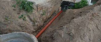
Underground low pressure pipeline
But, on the other hand, it is more difficult to notice a leak in the gas pipeline area, and even in it itself, than in communications with medium or high pressure
And it is important to remember this when using such a pipeline.
Due to the peculiarities of this type of communications, the security zones of the low-pressure gas pipeline are 2 m in each direction. It's quite a bit. However, in the event of an accident, the leak rate will be small. This explains the current standard.
If you need to lay such an external gas pipeline, it is worth taking into account the current standards for sanitary protective distances to various objects. These standards, established and approved by the government, are presented in the table below. Valid for the current year and, most likely, will be relevant for many years to come.
| An object | Distance from gas pipeline |
| House | 2 meters |
| Road | 3 meters |
| Water pipes | 1 meter |
| Sewerage | 1 meter |
| Power lines (1–35 kV) | 5 meters |
The pressure in such an external gas pipeline reaches 0.005 MPa. This, of course, is not much. However, in the event of an accident, gas will still begin to leak out quite quickly. So if you find it, you should fix the problem as soon as possible.
Moreover, the rush required is no less than in the case when a high-pressure gas pipeline breaks through. If only because in a system with low pressure it is more difficult to assess how much gas has already leaked.
Of course, such a gas pipeline is the easiest to organize. This is understandable, because with such a small security zone there are many more route options than a gas pipeline with medium or, especially, high pressure.
Standards for indentation from a pipe with low gas supply pressure in accordance with SP and SNiP standards
It is important to understand that maintaining the sanitary zone in this case is no less important than with the other two types of gas pipelines. Each option requires responsibility and maintenance
The rules are regulated by SP 62.13330.2011 and SNiP 42-01-2002, as well as standards for other systems. For example, on water supply (SP 31.13330.2012). Also, all this is regulated by the establishment of rules, in accordance with Government Decree No. 878 of November 20, 2000 regarding gas distribution.
Additional standards
All norms of distances from the gas pipeline to communications were taken care of by the adopted resolutions. There are reference tables in the PUE standards and the minimum distance provided for gas pipes in main pipelines, residential and industrial buildings.
Power supply cables
Everything about specific cases that may constitute an increased danger - from a huge overpass to an electrical outlet located dangerously close to a thin gas pipe connected to a cooking stove - depends on the type of cable and voltage, gas pressure and its type. If in doubt, it is always better to play it safe and check your calculations with a specialist than to endanger the world around you.
Laying a gas pipe underground: technology, GOST, video
To lay an underground gas pipeline, it is necessary to ensure that the roadway is blocked, and the company that installs the gas pipeline underground, using road designs, draws a site plan for the location of the equipment and in the drawing indicates the exact geometry of the objects that are adjacent to the buildings. This will ensure that traffic signs are correctly positioned to restrict travel along the highway or onto areas of land where an underground gas system is planned to be laid.
This arrangement of prohibition signs must be agreed upon with the territorial authority of the road inspection, which, in turn, if a positive decision is made, must issue a permit for the installation of highways underground.
laying a gas pipe along an area above ground
Recommendation tips for laying
So, when performing installation work, the following is taken into account
1. The gas system must be laid at a depth level of at least 80 cm to the top of the structure (box). In areas where the passage of agricultural combines and equipment is not provided, a depth of at least 60 cm is allowed for underground structures.
2. For areas that are unstable to erosion and landslides, the depth level where the gas pipeline will be installed must be no less than the boundaries of the area where destructive processes are possible, and no less than 50 cm below the level of the sliding surface.
3. In areas where highways and communication systems underground for various purposes intersect, highways transmitting a heat source, ductless systems, as well as in areas where a gas pipeline passes through the walls of wells, the structure must be placed in a box or case. If it intersects with heating networks, then installation in a metal box (steel) is required.
4. If there are structures with different pressure indicators in a populated area, the box should be installed at the level of utility networks, which are located underground and which, in turn, are located below the level of the gas pipeline. The ends of the box must be routed in both directions from the outer walls of the communication systems, taking into account the gap, which should not be less than 2 meters. If there is an intersection with a well, the gap must be maintained at 2 cm. Using waterproofing, it is necessary to place plugs at the ends of the box.
5. At the top point of the slope (except for the area where the walls of the well intersect) on one side of the box, it is necessary to build a control tube, which will be located under the protective device.
6. It is not prohibited to lay an operational cable (for example, an electrical protective wire, a communication cable) in places between the structures of the system and the box, which is intended for servicing distribution networks.
laying a gas pipe around the site with your own hands
Distinctive features of the product
In construction work, building elements and pipes made of polyethylene are used, which have a safety indicator for such a property as strength, no less than 2. Such elements are installed, their pressure indicator is at around 0.3 MPa, in populated areas (cities, villages) and its circumference.
The products must be laid using polyethylene connecting units and gas ones with a safety indicator of at least 2.6. When laying systems whose pressure drop is in the range of 0.306 MPa in populated areas, it is necessary to use connecting units and pipes that have a reserve strength index of at least 3.2.
laying a gas pipe underground in a private house
Commissioning of intra-house gas pipelines
Responsibility for the condition and proper operation of indoor gas equipment and gas pipelines in cities and towns lies with the operating organizations of the gas industry. Departmental and private houses are serviced by the relevant housing administrations (housing office), gas operating organizations (under agreements with them) or house owners.
The main form of maintenance of gas equipment in a residential building is periodic preventive inspection and repair of gas appliances and the intra-house gas pipeline, carried out on a scheduled basis and at the request of consumers. The following frequency of preventive inspection in residential buildings has been established: control pressure testing of gas pipelines is carried out once every 5 years, the timing of preventive inspection of intra-house gas pipelines is established by the gas authorities in agreement with Gosgortekhnadzor, current repairs are carried out once a year, lubrication of taps and refilling of seals on risers and inlets — once a year, lubrication of taps on devices — during the period of preventive maintenance.
Preventive inspection of gas stoves and high-speed water heaters is carried out once every 2 months. Capacitive water heaters, heating, heating and cooking stoves and other devices with an automatic device are inspected once a month.
During a preventive inspection, the following work must be performed:
* inspection of all gas pipelines starting from the tap at the inlet, washing all connections in order to check the condition and tightness of connections and fittings on the gas pipeline - at each scheduled visit;
* lubrication of taps at the inlet, branches to apartments and risers - as necessary;
* checking the fastenings on the gas pipeline - at each visit according to the schedule;
* checking the operation of gas appliance fittings once every 3 months;
* removing the burners and cleaning the nozzles - one by one; re necessary;
* checking the connection density - at each scheduled visit;
* adjustment of all stove burners - as needed;
* checking the serviceability of the automatic block tap and automatic safety systems for instantaneous water heaters - according to the schedule;
* regulation of water and gas supply with checking the operation of the water heater in different modes - according to the schedule.
Great Encyclopedia of Oil and Gas
Gas inlets into buildings from the yard line or street network are laid in stairwells or basements. In residential buildings, inputs are arranged separately for each section. When laying pipes through the foundation masonry, measures are taken to protect them from destruction during settlement of the building. The pipe located in the wall is wrapped with resin rope and placed in a case - a pipe of larger diameter.
It is preferable to make gas inlets into houses in the basement. Entering gas pipelines into basements and semi-basements and laying gas pipelines along them (if there are no special technical corridors) is prohibited. It is not allowed to install plugs on basement and intra-house gas pipelines.
The gas inlet can be made not only into the stairwell, but also into the non-residential basement of the building.
Gas inlets of gas tanks are passed through special chambers in which shut-off valves, gas protection, valves for manual discharge and control valves for releasing gas into the atmosphere when gas tanks overflow are placed, as well as heating system control units and non-flammable gas pipeline valves for purging gas tanks and gas inlets.
Recessed steel gas inlets installed under buildings must be enclosed in a gas-tight cartridge. The latter must be located in an accessible and commonly used part of the building. Where the cartridge ends, the annular space between the cartridge and the inlet pipe must be sealed to prevent gas leakage.
Low-pressure gas inlets of short length (up to 25 m) are allowed to be put into operation without testing them for density under air pressure. In this case, the density of the gas pipeline (input) is checked in an unfilled trench under operating gas pressure by coating the connections with soap emulsion or another equivalent method.
| Yard gas pipeline diagram. /, 2, 3, 4, 5, 6, 7 and 8 – gas risers. |
A gas inlet is a gas pipeline running from the distribution (street) network to the riser of the intra-house gas network.
| Yard gas pipeline diagram. 1, 2, h, 4, 5, v, 7 8 – gas risers. |
A gas inlet is a gas pipeline that runs from the distribution (street) network to the riser of the indoor gas network.
| Yard gas pipeline diagram. |
A gas inlet is a gas pipeline running from the distribution (street) network to the riser of the indoor gas network.
Gas inlets and risers are purged sequentially, starting with the most distant inlet and riser.
Since there are gas inlets into the building on each of the two staircases, and the gas pipeline layout in the left half of the building completely coincides with the distribution in its right half, the gas pipeline diagram can only be drawn up for half of the building.
Pages: 1 2 3 4 5
Analysis of the main parameters of the gas supply system
Indoor gas pipeline network
The gas supply system has a dead-end circuit.
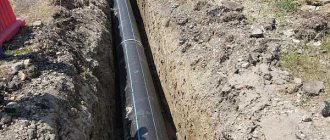
The laying of external gas pipelines is adopted underground. A low pressure gas pipeline is laid in a trench. The bottom of the trenches is leveled with a layer of coarse sand 10 cm thick, and after laying the gas pipeline is covered with sand to a height of at least 20 cm.
To determine the location of a gas pipeline using the instrumental method, an insulated satellite wire is placed directly on the gas pipeline.
The gas pipeline is laid with a slope of at least 0.002% to remove moisture released from the gas. In lower parts of gas pipelines, condensation pots are installed in which the released moisture accumulates.
At the gas pipeline exit from the ground, a PEF63/StF57 base input is provided, with a permanent PE/ST connection. Gas is supplied to the residential building from the courtyard facade.
Installation of disconnecting devices is provided on the wall of the building at the exit of the gas pipeline from the ground at a height of 1.8 m from the ground. Steel ball valves with an insulating connection are used for installation.
The above-ground steel gas pipeline is coated with a paint coating consisting of 1 layer of primer “Universum” Finish A10 and 2 layers of methyl methacrylate enamel “Universum” Finish A12..
The designed low-pressure gas pipeline is made from the point of insertion into the existing low-pressure gas pipeline. The pressure at the insertion point is 1.8 kPa.
The pipes are connected by welding. The types, structural elements and dimensions of welded joints of steel gas pipelines comply with GOST.
Intra-house gas pipeline
Installation of internal gas equipment is carried out after the following work:
— installation of interfloor ceilings, walls and partitions on which gas pipelines, fittings, gas equipment and appliances will be installed;
— construction of holes, channels and grooves for laying gas pipelines in foundations, walls, partitions and ceilings;
— plastering walls in kitchens and other rooms where gas equipment is installed;
Internal gas pipelines are installed from steel pipes. Pipe connections are made by welding. Gas pipelines are laid openly.
The gas pipeline - collector is laid along the outer wall of a residential building between the windows of the 1st and 2nd floors at a distance of 3.25 m from the ground. The diameter of the gas manifold running along the outer wall of the building is assumed to be constant and equal to 57 mm in accordance with hydraulic calculations. The risers are accepted with a diameter of Dу = 25 mm and are placed on the outer wall. They are laid vertically. The permissible deviation is no more than 2 mm per meter of gas pipeline length.
It is prohibited to lay risers in residential premises, bathrooms and sanitary facilities.
Shut-off devices are installed on risers and in front of gas appliances.
There are a total of 4 risers in the building.
Enclose the gas pipeline passing through the wall and ceiling in a case. The diameter of the case is assumed to be 57 mm. The space between the ceiling and the casing is sealed over the entire thickness of the structure with mortar. The ends of the case are sealed with elastic material. In the case, the gas pipeline is painted with oil paint in two layers. The case itself is filled with resin tow and filled with bitumen. The edges of the case protrude 3 cm above the floor and do not protrude from the ceiling.
Apartment distribution of the gas pipeline is carried out along the walls at a distance of 55 cm from the ceiling and 5 cm from the wall for ease of operation.
To account for gas consumption in kitchens, Grand-4 gas meters are installed at a distance of 1 m from the gas stove, mounted vertically at a height of 1.7 m from the floor level.
The disconnect devices are mounted in front of the gas meter at a height of 1.95 m from the floor level. The gas stove is attached to the gas pipeline using a rigid connection (pipe).
In the kitchen, the gas stove is installed permanently on a flat surface. A 4-burner stove has been adopted.
For the removal of combustion products, prefabricated chimneys are provided, which are discharged above the roof of the building and end in a deflector. To ventilate the room there is a window with a glazing area of 1.53 m2.
Which method to choose: underground or aboveground?
The choice of installation method depends on the specific case, namely: on the characteristics of the soil, climatic conditions, built-up area, etc. Therefore, it is impossible to give an unambiguous answer to this question.
Let's consider the basic tips for choosing a method for laying gas pipelines:
- If the soil on the site has a high corrosion coefficient, then it is recommended to install the gas pipeline above ground.
- If there is a high-voltage power line near the site where installation work will take place, the pipes are laid underground.
- if the gas pipeline is supposed to be laid through the territory of neighboring areas, then it should be done in an open way (overground).
- In addition, if the gas pipeline will be laid through a roadbed, it is advisable to choose a combined pipe installation option. The combined option includes: underground laying under the roadbed and above-ground laying throughout the site. Thus, an optimal solution to the problem is obtained.
In most cases, an underground method of laying pipes is used to protect the pipeline from the effects of various negative factors.
Depending on which method of installing gas pipeline communications will be carried out, pipes made of different materials are used. There are two types of gas pipes based on the material of manufacture:
- steel;
- polyethylene (PE);
Steel pipes are versatile - they can be used for any installation (above-ground and underground), but modern polyethylene products are used for underground installation of gas pipelines. This is due to the fact that polyethylene has poor resistance to ultraviolet radiation. Under the influence of ultraviolet rays, polyethylene loses its properties and is destroyed
However, it has a number of useful advantages that are worth paying attention to.
Options for laying gas pipeline systems
Today, there are three main options for installing gas pipeline structures:
- underground (closed);
- aboveground (open);
- interior.
The depth of the gas pipe on the site depends on the type of gas that will be transported through it
Closed method. This method of laying gas pipelines is the most common today. The depth of laying the pipe depends on the gas moisture content. If wet gas moves through the pipe, then it is laid below the freezing level of the soil. A pipe with dry gas is installed 80 cm below ground level. All necessary restrictions, including the distance to a residential building, are described in the relevant regulatory documentation (SNiP 42-01-2002). Using a closed method, you can install pipes made of steel or polyethylene.
Open method. As a rule, this method of laying gas transportation communications is used if it is impossible to install the system underground due to the presence of natural or artificial barriers. Such barriers include:
- bodies of water;
- ravines;
- various buildings;
- other communications.
For open installation, it is allowed to use only those pipes that have high strength. This description includes steel products, which are the main structural elements of such systems. The distance of an open steel gas pipeline to a residential building is not established.
Internal method. This method of laying gas pipeline systems implies their location indoors. In this case, the distance to the walls and to other objects inside the room is determined depending on the specific case. When laying gas pipelines internally, their installation inside walls is prohibited. For the arrangement of internal gas structures, pipes made of steel and copper are used.
For open installation, only metal pipes are used
Types of base inputs
There are three types of gas pipeline exit points from the ground, as well as their options - with or without a case. All presented designs are intended for installation in places where the gas main exits from the ground, and are suitable for gasification of residential buildings, that is, low-pressure networks.
Let's take a closer look at how they differ.
Option #1 – L-shaped
This is the most common type of design, shaped like the letter “L” and reminiscent of a poker. It is usually made from two types of pipes - steel and polyethylene. The steel part is cold bent, without welds, and protected from corrosion by extruded polyethylene or other moisture-resistant material.
Diagram of the central heating system indicating the material of manufacture and methods of connecting the structure to the pipes. The monolithic polyethylene-steel assembly is located on a horizontal, underground section of the product
The location of the permanent connection underground, on a horizontal section, protects it from freezing in frosts typical of northern regions with a harsh climate.
Products are manufactured in factories, where they are covered with a layer of insulation. Already on site, the connecting nodes are protected with adhesive polymer tapes, the layer thickness is at least 1.8 mm
In addition to conventional designs, products with transitions are produced. This is a metal part with a standard diameter of 25 or 32 mm, made by rolling and secured by welding.
Option #2 – i-shaped
The material for the production of i-shaped structures is the same as for the production of L-shaped analogues - polyethylene and steel pipes of GOST standards. They are also intended to ensure gas supply to residential buildings - dachas, cottages.
A special feature of the products is the location of the polyethylene-steel transition. It is not located on the horizontal part, like the alternative L-shaped product, but on the vertical part, but underground.
Scheme of i-shaped base input. Due to the location of the permanent connection on the vertical part, the product is suitable for installation in any type of soil
To protect the connection, thermal insulation and a metal case are used. i-shaped structures, even the most insulated and insulated, have temperature restrictions. They are installed in areas where the air temperature in winter does not drop below -15°C.
Residential gas connections are usually low pressure, but the i-inlet is suitable for medium/high pressure fuel supply.
Option #3 - straight
The main difference between the direct exit of a gas pipe from the ground is that it consists entirely of polyethylene, which ensures free bending. The second feature is its use only for the residential sector, since it cannot withstand the supply of medium and high pressure fuel.
The polyethylene-steel transition is located at the top, on the vertical part of the product. To protect against mechanical damage and exposure to atmospheric agents, it is enclosed in a durable metal case.
Direct inputs are located near residential buildings, in close proximity to the connection point of household appliances - boilers, stoves, ovens.
The main guideline is regulatory documentation
In the future, during scheduled inspections or in the event of an emergency, regulatory authorities will carefully inspect all components, from the insertion into the central pipe to the connection of the gas boiler, stove or oven
And the first thing they will pay attention to is whether the installation method is chosen correctly - above-ground or underground
A more acceptable, but also expensive way to supply fuel to the house is underground. It is practiced if the pipe is not subsequently affected by factors such as seismic activity, groundwater, or road surfaces crossing the path.
The basement input is an element of underground installation, therefore, further we will only talk about it.
But the integrity and correct equipment of the gas pipe exiting the ground are important not only because of the risk of receiving a large fine during the inspection. The main thing is to ensure the safety of the residents of the house and everyone nearby.
Any faulty equipment threatens a serious accident on the gas pipeline. In addition, if the basement inlet is not properly designed, a gas leak may occur, and this will result in additional expenses from the family budget.
The gas line is brought out from underground to the outside directly near the wall of the building to ensure the shortest path to the end point - the boiler, which is located in the kitchen or in a separate room
When laying main pipes, installers are guided by the provisions set out in Russian regulatory documents. For example, SNiP 2.04.08-87* considers all the nuances of installing polyethylene pipes, preferable for private use, as well as the requirements for their laying routes.
The depth of laying the gas pipeline is also regulated here - 0.8 m. The exception is for territories where traffic is not expected - 0.6 m. These data must be taken into account when choosing the size of equipment for installing a gas pipeline out of the ground, although factory products are usually adjusted to standard scale.
It is undesirable for underground water to be present near the installation site of the input unit. If they still exist, measures must be taken to prevent deformation or floating of the polyethylene pipe.
Specific information about underground gas pipelines can be gleaned from SNiP 42-01-2002. It contains useful materials on the use of cases - special protective elements, as well as on the conditions for using polyethylene pipes.
It is interesting that two or even more gas lines can be located in one trench, but in such a way that it is possible to freely access each of them during repairs
While laying pipes, workers may encounter the gas pipeline intersecting with other utility networks. This does not cause any difficulties, since the permissible distance between the networks is only 20 cm.
All stages of construction, from project development to acceptance into operation, must be carried out in accordance with the standards of SNiP 3.02.01-87, PB 12-529-03 and SP 62.13330-2011.
Features of inserting into a metal gas pipeline
The insertion into the central branch of metal pipes is carried out after drawing up a sketch of future work and preparing all the materials that will be useful in the process based on the chosen connection method.
The first thing to do is clean the work surface. At the same time, absolutely everything unnecessary is removed from the place chosen for connection to the gas pipeline: debris, paint, rust. Next, mark the insertion site, making marks. Make the necessary holes.
After this, the wells are well treated. When cutting the surface of the pipe, the cracks are carefully coated with clay. This is required to minimize the risk of igniting escaping gas while making the cut.
The holes made are sealed as soon as possible with an asbestos-clay plug, and the area being treated is quickly cooled.
Pipe connections should be made in such a way as to achieve extremely accurate intersection of the pipeline axes
The next stage of work will be the installation of a disconnecting device. After the metal has cooled, remove the plug in order to be able to remove a section of the cut pipe from the gas pipeline.
Now, a disconnecting device is installed in the resulting gap. It consists of a set of rubber and wooden disks and bags filled with clay of a viscous consistency.
Next, install the pipe. Having closed the hole with a disconnecting device, they begin to make the main hole intended for connecting a new pipe. First of all, it is necessary to check the diameter, since sometimes the markings have to be adjusted.
Next, make a hole and install the pipe. Its butt joints are welded on both sides and the valve on it is closed. Afterwards the holes are sealed.
Having completed the installation of the pipe, begin welding the new pipe. Before this, the metal slag formed after making the main hole is removed. Having cleaned the surface of the pipeline, install a new pipe in the holes and, covering it with clay, make welding seams.
Next, take an aqueous solution of soap and carefully coat the new seams with it, making sure that they are tight and that there is no leakage of blue fuel.
Pipe joints should be carefully checked for leakage of blue fuel by lubricating them with a solution of soap and water.
If no gas leak is observed, proceed to the final stage of work, that is, backfill the trench. However, this is not such a simple operation as it seems at first glance.
Backfilling of the trench must also be carried out in accordance with the standards given below:
- around the circumference of the insertion point of the ball valve and the connecting pipe, it is necessary to backfill soft soil with a layer more than 20 cm thick and compact it;
- It is strictly forbidden to use a bulldozer or other heavy construction equipment to completely fill the trench with soil.
The collision of the mentioned equipment with the layer of soil covering the insertion point and the pipes coming from it, as well as with the ball valve protruding above the soil surface, is strictly prohibited.
What influences the preparation of the project
If special skills are lacking, independent design is undesirable and unlikely to be feasible. In the process of working on a project, many factors that are known only to specialists must be taken into account.
Among them are:
- depth of groundwater, soil specifics, landscape and climatic features;
- the depth at which the central route runs;
- distance from the pipeline to the building, taking into account the depth of the outlet;
- SNiP requirements for equipment and connection points.
In addition to what is listed in the project, the method of laying the pipeline, the diameter of the gas pipeline, the required set of instruments and fittings, the materials used, the features of the joints and internal wiring must be shown.
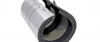
Bitumen VUS
Very reinforced bitumen insulation is used as waterproofing and a way to prevent corrosion on steel pipe lines in non-channel types of laying water supply lines and industrial pipelines.
The main area of use of existing coatings is the prevention of corrosive formations in a network of small-diameter pipes that operate at normal temperatures.
The multilayer structure of bitumen-mastic treatment consists of:
- primer on the surface of the pipes;
- the first layer is reinforced fiberglass;
- the second layer consists of bitumen mastic, which consists of hydrophobic materials;
- the next reinforcing layer consists of fiberglass;
- a pair or a single layer of coating consisting of kraft paper.
Video
Very reinforced bitumen-polymer insulation has the following advantages:
- Easy to apply.
- Great level of durability.
- Resistance to mechanical damage.
- Resistant to cathodic disbondment.
- Excellent adhesion characteristics to steel parts.
- Minimum oxygen and water permeability.
- Resistance to corrosion formations.
- Tolerance to temperature changes.