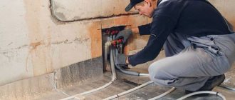
Organizing water underfloor heating is not a cheap undertaking. To realize all the benefits of surface heating, the homeowner has to bear the cost of purchasing large quantities of pipes, installing them and installing a cement screed. You won’t be able to save money on this, but it is quite possible to assemble the most expensive component of the system with your own hands - a manifold for a heated floor. Let's look at the options for homemade distribution combs and figure out how you can make them yourself.
Assembling the factory manifold
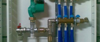
To save on the price of heating equipment and make a collector unit yourself, you need to understand what factory-made products are made of. The kit includes the following parts:
- A distribution element for connecting a supply line to 2 or more outlets, equipped with Eurocones (fittings for connecting pipes). In most cases, it is equipped with transparent flasks, where the coolant flow in each circuit is visible (rotameters).
- The same for connecting to the return line. Instead of flow meters, there are thermostatic valves controlled manually from servo drives or thermal heads of the RTL type. Their operating principle is simple: when you press the spring-loaded rod, the flow area narrows, and the flow of water through the element decreases.
- Automatic air vents installed separately on the supply and return manifolds.
- Taps with plugs for emptying and filling circuits with coolant.
- Thermometers that record the total supply and return temperatures.
- Shut-off ball valves and mounting brackets.
Construction of a collector group for heated floors
For reference. On sale there are manifold units with rotameters on the return line, thermostat valves that regulate the flow. Changing the layout does not affect the operation of the heating circuits.
When purchasing a comb, you can change the complete set depending on your budget and connection diagram to the boiler. For example, buy a distributor without rotameters, install 1 thermometer instead of two, or place the unit in a control cabinet.
Factory kits are manufactured in such a way that the manifold for heated floors can be easily and quickly assembled with your own hands. Judge for yourself: the distribution elements are already assembled, you just need to connect them to the heating circuits and install the auxiliary parts according to the diagram. How to do this correctly, see the following video:
In addition to brass and steel products, there are varieties of combs made from plastic sections, as shown in the photo. Their installation is carried out in the same way, except with more caution when tightening. Please note that the main threaded connections on the groups for draining water and connecting pipes do not need to be packed with flax or FUM tape; rubber seals are provided almost everywhere.
Plastic distributors with installation kit
Pipe selection
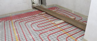
Although pipelines made of various materials can be used to supply water and install circuits, in everyday life they mainly use polymers, which are supplied in coils of various lengths and are easily bent when laying loops.
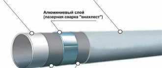
The main materials of heating pipelines are: metal-plastic made of cross-linked polyethylene PEX with an aluminum layer between the inner and outer shells, cross-linked PEX and heat-resistant PE-RT polyethylene.
It should be noted that metal plastic is not very practical as a material for heated floors - due to its high rigidity, it is difficult to bend with a small radius, and mechanical impact on the surface during installation or before laying the screed leads to bends and breaks. You can repair a metal-plastic pipeline by inserting a section connected using compression or crimp fittings - this leads to a decrease in the passage channel and an increase in hydraulic resistance.
Pipes made of cross-linked and heat-resistant polyethylene have the same service life of about 50 years; it is believed that the PE-RT pipeline is easier to install in rooms with low temperatures, and if damaged, it can be easily repaired by soldering, although the technology is not very well known. Also, the cost of PE-RT is lower than cross-linked polyethylene PEX, although there are enough products of both categories at a relatively low price on the construction market.
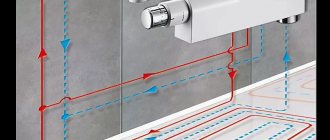
Rice. 19 Basic pipe laying schemes for heated floors
How to save money on a mixing unit
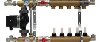
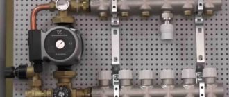
Many master plumbers consider it an integral part of the underfloor heating manifold, although these are 2 different elements that perform separate functions. The task of the comb is to distribute the coolant along the circuits, and the mixing unit is to limit its temperature to 35-45 °C, maximum 55 °C. The collector connection diagram shown below works according to the following algorithm:
- While the system is warming up, the two-way valve on the supply side is completely open and allows maximum water through.
- When the temperature rises to the calculated value (usually 45 °C), the remote sensor acts on the thermal head, and it begins to block the flow through the valve, pressing on the rod.
- After the valve mechanism is completely closed, the coolant, stimulated to move by the pump, circulates only in a closed floor heating network.
- The gradual cooling of the water is detected by a temperature sensor, causing the thermal head to release the rod, the valve opens and a portion of hot water enters the system, while some of the cold water goes back. The heating cycle repeats.
Note. If the manifold thermostats are controlled by servos, a bypass and bypass valve is added to the mixing assembly. The goal is to organize circulation in a small circle when the servos, for some reason, suddenly block all the circuits.
Good news for those who are very limited in funds, but want to heat themselves with warm floors: installing a two- or three-way valve with a pump is not always necessary. There are two ways to reduce the cost of the system by avoiding the purchase of a mixer:
- power the heating circuits directly from the gas boiler through the manifold;
- install RTL thermal heads on the manifold valves.
The manifold assembly, assembled from brass tees, provides for regulation by automatically limiting the reverse flow with RTL heads.
Let us immediately note that the first option contradicts all the canons and cannot be considered correct, although it is used quite successfully. The bottom line is this: high-tech wall-mounted gas boilers can maintain the temperature of the supplied water at 40-50 °C, which is acceptable for heated floors. But there are 3 negative points:
- In spring and autumn, when there is minimal frost outside, the boiler will not be able to lower the coolant temperature below 35 ° C, causing the rooms to become stuffy and hot due to heating of the entire floor surface.
- In the minimum combustion mode, the parts of the heating unit are covered with soot twice as quickly.
- Due to the same mode, the efficiency of the heat generator is reduced by 5-10%.
Advice. To avoid discomfort from the heat during transitional periods, you need to install traditional heating radiators in the rooms of a private house, and connect underfloor heating when it gets very cold.
Thermostatic heads of the RTL type operate on the principle of a two-way valve, only they are located on each circuit and are not equipped with remote sensors. A thermoelement that responds to changes in water temperature is located inside the head and blocks the flow along the circuit when it has heated up above 45-55 ° C (depending on the adjustment). In this case, the comb is connected directly to a heat source running on any type of fuel - wood, diesel or pellets.
Important condition. For normal operation of heated floors controlled by RTL thermal heads, the length of each circuit should not exceed 60 m. More details about the design of such heating and the correct collector assembly diagrams are described in a separate instruction and in the next video:
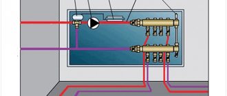
What is it needed for?
When installing water pressure systems, there is a rule: the total diameter of all branches should not exceed the diameter of the supply pipe . In relation to heating equipment, this rule looks like this: if the diameter of the boiler outlet fitting is 1 inch, then the system allows two circuits with a pipe diameter of ½ inch. For a small house heated only with radiators, such a system will work effectively.
In fact, there are more heating circuits in a private house or cottage: heated floors, heating of several floors, utility rooms, and a garage. When they are connected through a tapping system, the pressure in each circuit will be insufficient to effectively heat the radiators, and the temperature in the house will not be comfortable.
Therefore, branched heating systems are made using collector systems; this technique allows you to adjust each circuit separately and set the desired temperature in each room. So, for a garage, plus 10-15ºС is enough, and for a nursery, a temperature of about plus 23-25ºС is required. In addition, heated floors should not heat up more than 35-37 degrees, otherwise it will be unpleasant to walk on them, and the floor covering may become deformed. With the help of a manifold and shut-off temperature, this problem can also be solved.
Video: using a collector system for heating a house.
How to make a comb from polypropylene
A distributor welded from polypropylene fittings is the cheapest manifold for a warm water floor that you can think of. It has several disadvantages:
- the design is large in size and will not fit into every box, so it will have to be mounted on the wall in the boiler room;
- It is quite problematic to install flow meters, so there simply won’t be any;
- you need to be good at soldering polypropylene so as not to make a mistake at any of the many joints.
Conclusion. It makes sense to make a PPR comb when it is planned to be installed in a boiler room, and the number of outlets is designed for 3-5 circuits, otherwise the design will be too cumbersome. The dimensions can be judged from the photo, which shows a manifold with only 2 connections, the third outlet is for connecting the main line from the boiler.
To work, you will need no more than 2 m of PPR pipes with a diameter of 32 mm and the same tees according to the number of bends. In addition, polypropylene-metal threaded adapters, ball valves and straight radiator valves used for balancing are needed. Make a manifold for heating circuits of underfloor heating according to the instructions:
- Having carefully measured the depth of the pipe entering the tee and placing a mark on the outside, solder these 2 parts together.
- Set aside the same distance from the edge of the fitting along the pipe and cut it off and clean the end. Solder the adapter coupling to the lower branch of the tee.
- Repeat the operations outlined in paragraphs 1 and 2. Weld the resulting second block with the first, then move on to the third, and so on.
- Solder an elbow or tee at one end of the PPR for mounting an air vent, and at the other end - a coupling for a ball valve.
Examples of PPR collectors - for 3 and 9 branches
Advice. Weld the fittings close to each other, otherwise the structure will grow to unimaginable sizes and will look unsightly.
When the main welding work is done, all that remains is to screw the taps and radiator valves to the couplings, and put the automatic air vent in place. Details of the assembly of the unit are clearly demonstrated in the video:
Distributor made of metal fittings
If you use metal fittings instead of polypropylene, you will be able to slightly reduce the size of the structure and do without a soldering iron. But here another pitfall awaits you in the form of cheap thin-walled tees, which are scary to handle with a pipe wrench - low-quality material can crack. If you buy high-quality fittings, then the total price of the product will be closer to the factory manifold, although the savings will still remain.
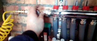
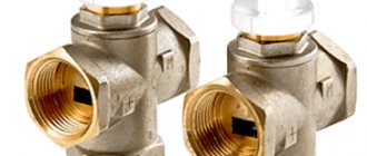
For manufacturing, you need to select internal/external thread tees made of good brass, shown in the photo, and ball valves with a low stem and a butterfly handle. The same radiator valves will go to the second part of the comb. The assembly technology is simple: pack the threads with flax or thread and twist the fittings together, and then install the taps and other parts.
Advice. When assembling, try to direct all the side bends in one direction, as well as the valve stems, so that the homemade manifold looks presentable. When screwing on pipeline fittings, remove the handles and adjusting caps so that they do not cling to adjacent taps.
Installing flow meters on a comb of brass fittings is a difficult issue. Then the supply line will have to be assembled from crosspieces and special adapters for rotameters will be installed. Some of them are also made for Eurocone, so the adapter will have to be machined. It is easier to balance the system without flow meters.
As you can see in the photo, there is nowhere to put the rotameter here
Is it worth making a collector yourself - conclusions
If you want to connect 3-4 floor circuits on a budget basis, then it’s definitely worth the hassle with polypropylene. Provided that the comb is planned to be placed in the boiler room, and not inside a beautiful cabinet somewhere in the corridor. Soldering must be done very carefully so that after 1-2 years your product does not leak.
When it is necessary to assemble a manifold for 8-10 underfloor heating circuits, use fittings made of high-quality brass. Of course, in terms of dimensions, such a product will be larger than the factory one, but it will allow you to save on the number of parts.
Disadvantages of the collector system
Note that collector wiring has one significant drawback - its high price. This option is one of the most expensive. Other disadvantages include that a DIY heating comb will not function without a circulation pump. You will also need a large number of pipes, since separate pipes go from the collector to each heating device.
Assembling a collector system and installing a heating collector is a rather labor-intensive process when compared with the installation of other types of systems, so additional costs await you here.
In general, the collector system is one of the most reliable and efficient heating systems. Despite the high cost and some disadvantages, this system is a fairly common option. Therefore, if the construction budget is somewhat limited, then it is better to give preference to a reliable heating system rather than expensive finishing.