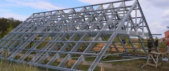
Metal structures consisting of lattice rods and a profile pipe are called trusses. For production, paired material is used, connected by special scarves. To assemble such a structure, welding is mainly used, but riveting is sometimes used.
The truss helps to cover any span. Length doesn't matter much. But in order to correctly perform such installation, competent calculation is required. If the welding work is completed efficiently and the plan is made without errors, all that remains is to deliver the pipe assemblies to the top. Then install them according to the top trim, strictly according to the markings.
Canopies can be made from a variety of materials:
- Tree;
- Concrete;
- Aluminum;
- Plastics.
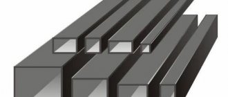
However, in most cases, the truss frame is made of a special profile pipe. This hollow structure differs from others in its high strength and simultaneous lightness. The cross-section of such a pipe can be:
- Rectangle;
- Square;
- Oval;
- Polyhedron.
For welding, trusses most often use a rectangular or square cross-section. This profile is less labor-intensive to process.
The maximum loads that a pipe can withstand depend on several factors:
- Wall thickness;
- Type of steel;
- Preparation method.
Profile metal pipes are made from special structural steel (1-3ps/sp, 1-2ps(sp)). Sometimes, when certain circumstances arise, galvanized steel or low-alloy alloys are used.
Pipes with a small cross-section are available in lengths of 6 meters. The length of large sections reaches 12 meters. The diameter of the pipe can be very different. The following are considered minimal:
- 10x10x1 mm;
- 15x15x1.5 mm.
The thicker the wall, the higher the strength of the profile. For example, products with very large dimensions (300x300x12 mm) are mainly used for the construction of industrial buildings.
What to pay attention to when calculating
Before you start calculating the cross-section of the pipe, you need to determine the optimal type of roof. The choice is influenced by its dimensions, the angle of the roof and the contour of the belts.
These above components depend on several conditions:
- Functionality of the building;
- What material are the floors made of?
- Roof slope angle.
Then the dimensions of the pipe are determined. Depending on the angle of inclination, the length is selected. Determination of the height is influenced by the brand of material from which the ceiling will be made.
The dimensions of the pipe also depend on the method of transportation and the total weight of the entire metal structure.
In the case where the calculation of a truss made from a profile pipe has determined that the length will exceed 36 meters, it is necessary to additionally calculate the construction lift.
Then the dimensions of the panels are determined. All calculations are based on the load that the structure must withstand. For a triangular roof, the slope should reach 45 degrees.
The calculation is completed by determining the exact distance between the elements of the metal structure from the profile pipe.
It is quite difficult to accurately plan everything in numbers without special knowledge. Therefore, it is better to turn to professionals who will carry it out on a computer. They always guarantee the high quality of their services.
Before starting construction, it is worth checking all calculations again, taking into account the maximum load that the structure can experience.
Important! In addition to the calculations made, the quality of installation depends on the correctness and accuracy of the plan drawings.
Calculation of trusses on a personal computer
Modern computing systems are based on the finite element method. With their help, calculations are made for trusses of any shape and geometric complexity . Professional software packages Stark ES, SCAD Office, PC Lira have wide functionality and, unfortunately, high cost, and also require a deep understanding of the theory of elasticity and structural mechanics. For educational purposes, free analogues are suitable, for example Polyus 2.1.1.
In Polyus, you can calculate flat statically determinate and indeterminate rod structures (beams, trusses, frames) for force action, determine displacements and temperature effects. Before us is a diagram of longitudinal forces for the truss shown in Fig. 2. The ordinates of the graph coincide with the results obtained manually.
Figure 9
In what sequence are the works performed?
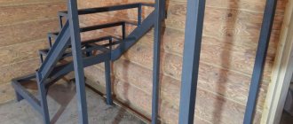
To assemble the frame, you must use the services of an experienced welder. Assembling a farm is considered a very responsible matter. You must be able to cook competently and understand truss welding technology.
It is very important to know exactly which units are best assembled at the bottom, and then lifted and secured to supports. To work with a heavy structure, you will have to use special equipment.
- First, the area is marked;
- Embedded parts are mounted;
- Vertical supports are being installed.
Quite often, metal pipes are lowered into a trench and then filled with concrete. A plumb line is used to check the verticality of the installation. To control parallelism, a cord is pulled between the last posts. All others are set according to the received line.
By welding, longitudinal pipes are welded to the supports.
The truss parts are welded on the ground. The belts of the structure are connected by jumpers and special braces. Then the finished blocks are raised to a certain height. They are welded to the laid pipes in the places where vertical supports are installed. Longitudinal jumpers are welded between the trusses directly along the slope so that the roofing material can be fixed. Mounting holes are made in advance in the jumpers.
The connecting areas are well cleaned. This is especially true for the upper part of the frame, on which the roof will then be applied. Then the surface of the profiles is processed. Performed:
- Cleaning;
- Degreasing;
- Primer;
- Coloring.
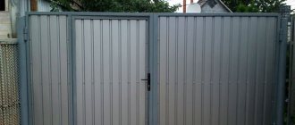
Entrance door and canopy
To calculate the dimensions of the cantilever canopy, you need to take into account the size of the porch. According to established standards, the size of the upper platform must necessarily exceed the width of the door (1.5 times). With a blade width of 900 mm, it turns out: 900 x 1.5 = 1350 mm. This should be the depth of the roof located above the entrance. In this case, the width of the canopy must exceed the width of the steps by 300 millimeters on both sides.
Cantilever awnings are most often installed over the entire area of the porch. They should cover the steps. The number of steps affects the size of the roof depth. The average value is determined according to the established SNiP standards: 250-320 mm. The size of the upper platform is added to this size. Moreover, the width of the canopy has a regulated value. The width of the steps is taken within the range (800-1200 millimeters), and 300 mm is added to it on two opposite sides.
We calculate the dimensions:
- Standard cantilever visor – 900-1350 mm by 1400-1800 mm.
- Cantilever-supported canopy over the porch, example of calculation for 3 steps and a platform: depth (900/1350 + 3*250/320) = 1650 – 2410 mm, width 800/1200 + 300 + 300 = 1400-1500 mm.
How are verandas calculated?
Typically such structures are located along the wall of a building. Several types of structures remain relevant for them:
- Beam-supported;
- Console.
The smallest depth is 1200 mm. 2000 mm is considered ideal. This distance corresponds to the location of the support pillar.
The calculation of the roof according to the perpendicular will look like 2000+300 mm. However, flat roofing is more suitable for areas where rainfall is minimal.
If the slope angle = 30 o. the leg adjacent to it (perpendicular depth of the canopy roof) is 2300 mm, the second angle is 60 degrees. Let's take the 2nd leg as X, it lies opposite the angle of 30 degrees. and according to the theorem is equal to half the hypotenuse, hence the hypotenuse is equal to 2*X, we substitute the data into the formula:
(2*X) 2 = 2300 2 + X 2
4*X 2 - X 2 = 5290000
X 2 (4-1) = 5290000
3*X 2 = 5290000
X 2 = 5290000.3
X 2 = 1763333, (3)
X = √1763333, (3) = 1327 mm – leg that will be adjacent to the wall of the house.
Calculation of the hypotenuse (roof length with slope):
C 2 = 1327 2 + 2300 2 = 1763333 + 5290000 = 7053333
C = √7053333 = 2656 mm, we check: the leg lying opposite the angle of 30° is equal to half the hypotenuse = 1327*2 = 2654, therefore, the calculation is correct.
From here we calculate the total height of the canopy: 2000-2400 mm is the minimum ergonomic height, we calculate it taking into account the slope: 2000/2400 + 1327 = 3327/3737 mm – the height of the canopy wall near the house.
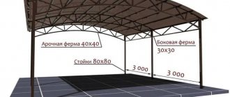
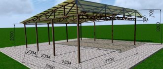
How to calculate parking
Typically, beam structures are installed. To make a canopy for your car with your own hands, you must first make a drawing, which should take into account the class of the car. The width of the parking lot should be equal to the size of the car, plus one meter on both sides. If two cars are parked, it is necessary to take into account the distance between them - 0.8 meters.
An example of calculating a canopy for a middle-class car, width – 1600-1750 mm, length – 4200-4500 mm:
1600/1750 + 1000 + 1000 = 3600/3750 mm – canopy width;
4200/4500 + 300 +300 = 4800/5100 mm – ergonomic length so that precipitation does not flood the site.
Calculation of the width of the canopy for two cars:
3600/3750 + 800 = 4400/4550 mm.
Signs of a zero rod
A rod in which the force is zero is called zero. There are a number of special cases in which a zero rod is guaranteed to occur.
- Equilibrium of an unloaded node consisting of two rods is possible only if both rods are zero.
- In an unloaded node of three rods, a single rod (not lying on the same straight line with the other two) will be zero.
Figure 7
- In a three-rod assembly without a load, the force in a single rod will be equal in magnitude and inversely in direction to the applied load. In this case, the forces in the rods lying on the same straight line will be equal to each other, and will be determined by the calculation N(3) = -P, N(1) = N(2).
- A three-rod unit with a single rod and a load applied in an arbitrary direction. The load P is decomposed into components P' and P" according to the triangle rule parallel to the axes of the elements. Then N(1) = N(2) + P', N(3) = -P.”
Figure 8
- In an unloaded node of four rods, the axes of which are directed along two straight lines, the forces will be equal in pairs to N(1) = N(2), N(3) = N(4).
Using the method of cutting out nodes and knowing the rules of the zero rod, you can check calculations made by other methods.
Gazebos
Typically, such a canopy is made in the depths of a personal plot. These structures are installed on a foundation, which can be:
- Pile;
- Columnar;
- Tape;
- Tiled.
The choice of foundation type is influenced by the size of the building, as well as the nature of the soil. These values must be shown on the drawing. The installed gazebo can have several sizes:
- 3x4 meters;
- 4x4 meters;
- 4x6 meters.
To independently calculate such a structure, to design a drawing, you need to take into account several parameters.
For one person to relax comfortably, 1.6-2 square meters is required. meter of floor area.
When installing a barbecue directly under a canopy, the recreation area should be separated from it by a free area. Its width is 1000-1500 mm.
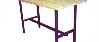
The width of a comfortable seat is 400-450 mm.
Table dimensions 800x1200. The calculation is per person (600 -800 mm). For a large number of people, the size can reach 1200x2400 mm.
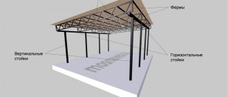
The most common material for rafters is wood, that is, wooden beams or boards. However, when constructing large buildings with a span length of more than 24 m and a slope length of more than 10 m, it is impractical and, often, impossible to use wooden rafters. They will not withstand the load from their own weight and roofing material. Therefore, in this case, metal rafters are used for the roof, which can be made from various profiled products. One of the most common options is pipe rafters, which can span a span of any required length.
As a rule, metal rafters are used in the construction of large industrial and public buildings. These could be hypermarkets, sports complexes, workshops, warehouses.
In individual construction, metal is practically not used for the roofs of residential buildings. Expensive, there are difficulties with installation and transportation. And it's not necessary. In this case, it is rational to use wood materials. However, in private construction there is a niche reserved for metal rafters (trusses). They are used in the construction of various canopies - for cars (covered parking lots), courtyard areas, swimming pools.
Among the advantages of metal trusses are:
- high strength to withstand heavy loads;
- ability to cover large spans;
- possibility of application on geometrically complex objects;
- durability.
The disadvantages are:
- heavy weight; when lifting trusses to a height, the use of special equipment is required;
- high price;
- low resistance to high temperatures, as a result of which, in the event of a fire, metal rafters (trusses) sag and collapse within 15-30 minutes.
Node calculations
All these types and other components of metal structures go through the design stage. That is, the calculation of all its main elements and details, I provide examples on my long-standing first website in the category calculation of metal structures, where you can look for my solutions. And it doesn’t matter what kind of production, industrial, public or agricultural building is designed from such solutions.
You may also be interested
Roof trusses over the assembly hall
A local engineering firm requested the service of developing CM drawings for metal roof structures. A typical
Checking the Column Base
The management of the design organization asked for a service. The goal, as it turned out, was to perform strength tests with calculations
Profile pipe is our option
In general, metal trusses are made from various products, as well as their combinations. For example, from channels, angles, I-beams, etc. And, of course, profile pipes.
What's good about the pipe? Its contours are highly streamlined, which minimizes wind pressure. This is important for tall objects subject to wind loads. Also, profile pipes are easy to paint; moisture (snow, frost, water) does not linger on their walls, so their resistance to corrosion is higher than that of alternative products. Accordingly, the durability is higher.
Despite the apparent massiveness, profile pipes are light, because there is emptiness inside them. This quality allows you to reduce the load of the roof structure on the walls and foundation. But it necessitates sealing these cavities at the ends of the products to prevent moisture from getting inside and, as a consequence, corrosion.
Metal profile pipes are made by rolling and processing metal on special machines. The cross-section of the pipes obtained in this way can be oval, rectangular, or square.
The material for profile pipes is usually structural steel. But in some cases, during the construction of special-purpose structures, galvanized steel or aluminum alloys are used.
The loads that a profile pipe can withstand depend on the type of metal used, the wall thickness of the product, and the manufacturing method.
The length of the pipes varies from 6 m (for small sections) to 12 m (for large sections). The minimum sections are 10x10 mm and 15x15 mm (with wall thicknesses of 1 mm and 1.5 mm, respectively). Pipes with this cross-section are used for light, small-sized structures (for example, small sheds). Increasing the wall thickness and cross-sectional dimensions leads to an increase in the weight and strength of the profiles. Therefore, pipes of maximum sections (from 300x300x12 mm and above) are used mainly for industrial buildings.
How to choose material and cook them correctly ↑
The creation and independent installation of canopies is possible with small dimensions of the structure. Trusses for canopies, depending on the configuration of the belts, can be made of profiles or steel angles. For relatively small structures, it is recommended to choose profile pipes.
Such a solution has a number of advantages:
- The load-bearing capacity of a profile pipe is directly related to its thickness. Most often, to assemble the frame, a material with a square cross-section of 30-50x30-50 mm is used, and for small structures, pipes of a smaller cross-section are suitable. Metal pipes are characterized by greater strength and yet they weigh much less than a solid metal bar. Pipes are bent - a quality necessary when creating curved structures, for example, arched or domed. The price of trusses for sheds is relatively small, so buying them will not be difficult.
- On such a metal frame you can conveniently and quite simply lay almost any sheathing and roofing.
Methods for connecting profiles ↑
How to weld a canopy
Among the main advantages of profile pipes, the non-shaped connection should be noted. Thanks to this technology, a truss for spans not exceeding 30 meters is structurally simple and relatively inexpensive. If its upper belt is sufficiently rigid, then the roofing material can be supported directly on it.
The formless welded joint has a number of advantages:
- The weight of the product is significantly reduced. For comparison, we note that riveted structures weigh 20%, and bolted structures weigh 25% more. Reduces labor and manufacturing costs. welding cost is low. Moreover, the process can be automated if you use devices that allow uninterrupted feeding of welded wire. the resulting seam and the attached parts are equally strong.
One of the disadvantages is the need to have experience in welding.
Bolt-on mounting
Bolted connections of profile pipes are not used very rarely. It is mainly used for collapsible structures.
The main advantages of this type of connection include:
- Simple assembly; No need for additional equipment; Possible dismantling.
- The weight of the product increases. Additional fasteners will be required. Bolted connections are less strong and reliable than welded ones.
Metal structures consisting of lattice rods and a profile pipe are called trusses. For production, paired material is used, connected by special scarves. To assemble such a structure, welding is mainly used, but riveting is sometimes used.
Construction of pipe trusses
The unit of a metal rafter system is a truss - a flat structure assembled from several straight rods. The outline of the truss is formed by the upper and lower chords. Between them there is a lattice consisting of braces and racks.
The truss elements - straight profile pipes - are connected either directly to each other or through knotted gussets. For fastening, welding, bolts, and rivets are used.
Metal trusses of standard sizes and designs can be purchased ready-made or assembled from pipes yourself. However, independent production requires high professionalism, the ability to work with metal structures and correctly make calculations. Therefore, for a private developer, it is much more convenient to purchase ready-made trusses, which only need to be installed correctly.
Choosing a truss, depending on the slope of the slope
The choice of design option is largely determined by the slope of the slope:
- 22-30°. To form slopes with a significant slope, triangular trusses are usually used. Their height is the span length divided by 5.
- 15-22°. The height is taken to be equal to the span length divided by 7. To increase the height of the truss structure, options with a broken bottom chord are used.
- Up to 15° . Typically, trapezoidal frames with a triangular lattice are used. The height of the truss block in such cases is determined by dividing the span length by a number ranging from 7 to 9.
Truss design options
Metal trusses can have different shapes, differ in purpose and ability to bear loads.
The fundamental elements of the truss are the belts - upper and lower. They create the outline of the structure, that is, they outline it from above and below. A belt is a straight or broken rod consisting of one or more spliced pipes.
In accordance with the contour of the chords, profile trusses are:
- with parallel belts (flat roof);
- trapezoidal;
- triangular;
- polygonal;
- segmental.
Trusses with parallel (horizontal) chords
- the simplest rectangular structures with horizontal belts of equal length. Contains many identical lattice parts of the same length. The design is completely unified. Since the belt of this type of trusses is set horizontally, they are used for the construction of flat roofs. Including for soft roofing coverings.
Trapezoidal designs
have the shape of a trapezoid (or two closed trapezoids). Used when constructing roofs with a slight angle of inclination. Truss nodes are characterized by increased rigidity and strength. There are no long rods in the central part, so the trapezoidal option is considered quite economical in terms of metal consumption.
Triangular trusses
shaped like a triangle, they are used to assemble the rafter system of gable roofs (canopies). The angle of inclination does not matter; it can be used for steep slopes. When assembling triangular trusses, the support units, which have a complex structure, should be carefully calculated and secured. Another feature: elongated rods are used in the central part of the structure. The steeper the sides of the triangle, the longer the rods. Therefore, their manufacture requires an increased amount of pipe.
Polygonal trusses
have complex outlines, reminiscent of an arch with a broken upper contour. They have increased strength, therefore they are used for heavy, bulky structures erected over large spans. Thanks to the special arrangement of elements, polygonal trusses allow you to save a significant amount of profile. But only when using them for heavy buildings. Lightweight structures when choosing a polygonal option will not benefit from the resulting savings.
Segment farms
are rare due to their complexity. They have an arched shape, with a curvilinear, semicircular contour of the upper belt. This outline follows the moment diagram, so a segmented truss requires a reduced amount of metal. However, again, the labor intensity of production associated with complex structural components makes it extremely unpopular.
In addition to the belts, the truss design includes a lattice - a combination of straight elements (posts, braces), which are located in a certain sequence between the belts and fasten them together. The strength of the truss, its weight, appearance and the degree of complexity of manufacturing depend on the type of lattice.
The following grating systems are common:
- triangular;
- diagonal;
- trussed;
- cross;
- rhombic;
- semi-diagonal.
Triangular lattice system
consists of elements arranged in repeating triangles. Suitable for trusses with parallel and trapezoidal chords. Support braces in a structure can be ascending or descending. The triangular system is characterized by the minimum total length of the lattice, as well as the minimum number of nodes with the shortest force path from the points of applied load to the support. The lattice contains long compression struts. In order for a structure with such braces to acquire the necessary stability, it is necessary to increase the amount of metal used during calculations. The increased consumption of the profile in triangular gratings is practically their only disadvantage.
Diagonal grille
– consists of a large number of braces and a small number of racks. The force from the place of the applied load to the support travels a long way, bypassing all the lines and nodes of the lattice. In this case, the braces should work in tension, and the racks - in compression. Due to the use of a large number of long braces, the design requires the use of an increased amount of profile. Such gratings are used in low trusses that must withstand great forces.
Truss grille
– complex in design and labor-intensive. It is used for high triangular trusses (4-5 m), which are designed for large spans (20-24 m). The arrangement of the elements in it makes it possible to reduce the length of the compressed rods.
Cross grid
– the braces are installed crosswise in it, with racks located between them. Such gratings are used in trusses that support double-sided loads. This type of load is typical for horizontal braced trusses of roofs of industrial buildings and bridges, vertical trusses of towers and masts.
Semi-diagonal and rhombic gratings
– these structures use two different bracing systems. This gives them increased rigidity. Such gratings are used in the structures of bridges, masts, and towers.
Welds
The recommendations given below are not mandatory; in any case, they are not contained in this form in the current regulatory documents. Nevertheless, compliance with these recommendations will significantly simplify not only the calculation but also the manufacture of trusses.
3.1. Nodal connections of GSP trusses are usually made without gussets
In this case, the truss lattice elements are welded directly to the chords.
3.2. The width of the lattice profiles may be slightly less than the width of the belt in the node in question
This allows you to significantly improve the quality of welding work using only fillet welds. If the difference in the width of the grid profile and the belt is significant, then it may be necessary to check the strength of the wall of the belt.
3.3. If the strength of the belt wall is not sufficient, then an overlay can be used to strengthen the belt wall
In this case, the overlay is welded to the belt, and the grille elements are welded to the overlay.