Fire hydrant – this is a means used to perform work related to extinguishing fires, which includes a set of equipment mounted on the internal fire-fighting water supply system (ERP) in the building (at the facility). The product consists of a valve assembly, body, cover, spindle, flywheel and gland seal.
Fire-fighting water supply systems with fire hydrants consist of the same elements as domestic and drinking water supply systems , but due to increased requirements for operational reliability, they have their own characteristics:
- fire-fighting water supply networks with more than 12 fire hydrants must be looped and connected to external networks with at least two inputs;
- in buildings with a height of 6 or more with a combined system of drinking water supply and fire-fighting water supply, fire risers should be looped at the top;
- It is recommended to connect the risers of a separate fire-fighting water supply system with jumpers to other systems for water change, if possible;
- Steel pipes are used to install fire-fighting water supply systems.
Purpose and main elements of a PC
The fire-fighting internal valve is most effective for extinguishing fires, especially at their initial stage. Therefore, despite the emergence of new, more technologically advanced means, it remains the main one. The equipment is designed to supply water to the source of fire. The profile RD regulates what elements a fire hydrant includes:
- shut-off valves, represented by a valve with a regulator;
- hose for transporting water;
- fastening element;
- guide barrel;
- storage cabinet.
This is a basic kit, which in some cases is supplemented with other elements: pump, automation, levers, sensors and other components.
Construction of an individual model of a fire water supply system
For individual infrastructure facilities, for example, oil storage facilities, chemical plants, port facilities and air terminal complexes, specific water supply systems for fire extinguishing are designed. Such facilities include not only a standard water supply with a hydrant.
These may include:
- Reserve fire reservoirs,
- direct pressure stations;
- filtration stations;
- automatic fire extinguishing systems.
- Underground water storage and above ground reservoirs;
- Railway tanks.
Parts requirements
Everything that goes into a fire hydrant kit must not only be functional and reliable, but also provide a continuous supply of water under extreme emergency conditions. It is these circumstances that determine the requirements for details:
- the connection head must not have defects that weaken the connection;
- the barrel must withstand a pressure of 0.65 MPa and form a compact jet;
- the sleeve must be complete and ready for use, for this it is folded with a double roll or accordion, without bends or kinks, and placed in a movable cassette with a rotation angle of at least 90 degrees;
- The cabinet is made of non-combustible materials, mainly sheet steel, and can be equipped with a lock.
The valve, as the main element of the internal fire hydrant device, should be considered separately and in more detail.
Main equipment components
What does the faucet device consist of?
A special fire cabinet will help minimize the external impact on the fire hydrant. The PC itself includes several elements:
- Shut-off valves.
- Connection head.
- Fire hydrant.
- Trunk.
Additionally, the PC can be equipped with a special lever that will facilitate opening the valve. If the PC comes with a pump to increase the pressure inside the system, the fire hydrant is additionally equipped with a remote control to activate this pump. As a rule, such pumps are used if the pressure in the water supply system is quite low. Other fire hydrants are also equipped with position sensors that operate from the network.
Fire hydrant equipment
The shut-off valve is often associated with the entire fire hydrant, but this is not true. This is not true, even though it is its main part, and itself consists of several elements:
- Housing and cover.
- Internal shutter.
- Flywheel.
- Threaded shaft.
- Seal.
There is a hexagonal coupling on the shutter valve body, which allows you to install this element on the water supply. To securely fix the shutter valve in the system, a fitting is prepared.
Installation and equipment of a fire hydrant
Next, we will consider the requirements and rules for installing and completing a fire hydrant. In some cases, installation is carried out using welded steel pipes, and in others using polymer products.
Installation requirements according to GOST
Most often, the fire hydrant is located in the most convenient place that all employees of the enterprise/company, etc. know about. A fire cabinet with all the necessary equipment is installed in such a place. If this is not possible due to the geometric features of the room, then the fire hydrant must be moved as close as possible to the ERW outlet.
In order to quickly increase the water pressure in the ERW, special buttons for starting fire pumps or stations are installed next to the fire hydrants. We especially note the following rules:
- All PC elements must be in working order;
- The working unit must always work smoothly, and for this it is lubricated with synthetic substances;
- Oil seals, seals and gaskets are regularly replaced;
- It is prohibited to install a fire hydrant with the flywheel facing down;
- Do not leave the tap in an intermediate position. It must be either completely open or completely closed.
Equipment requirements
The minimum equipment of any fire hydrant is a shut-off valve, a fire hose up to 20 meters long and a fire nozzle, completely ready to extinguish the flame.
According to SP 10.13130.2009, in fire cabinets there must be portable fire extinguishers next to the taps.
What should the valve be like?
The fire extinguishing agent itself is sometimes referred to as a shut-off valve. This is the main thing that a fire hydrant consists of. The fittings consist of the following parts:
- frame;
- body cover;
- spindle;
- flywheel mechanism;
- closing element;
- sealing element.
For connection with the water supply, a 6-sided coupling is installed on the body, and a fitting is provided for connection with the barrel. A simple device also implies a simple principle of operation. Namely: the shutter raises or lowers the spindle, which is driven by the flywheel. The result is the closing or opening of the water supply hole. Detailed requirements for shut-off valves are set out in GOST 53278-2009. The document offers a drawing, description and technical parameters.
Important! The design of the equipment must ensure smooth spindle movement. It is strictly forbidden to install cork or ball mechanisms in the fire extinguishing product. The best performance is achieved by a design with a spool that moves in the same direction as the water flow.
If the faucet uses devices that do not provide a smooth opening, the hose may tear or it will quickly fill with water and become straight. During a fire, such consequences will cause loss of time and intensification of the fire, as well as injury to the person using the fire extinguishing agent. Mostly the valve is made of brass or cast iron, the body is made of cast iron or metals with anti-corrosion coating, the shaft and threads are made of materials with parameters no lower than those of brass. The service life of the equipment should not be less than 5 years.
THE PROBLEM OF ELECTRIC CONTACT PRESSURE GAUGES
The third situation leading to non-standard operation of the ERW installation is the incorrect use of electrical contact pressure gauges (ECM). For all their advantages (visibility and ease of setting up the system), their main advantage is their relatively low cost.
ECM also has disadvantages in the form of “contact bounce”, oxidation of contact elements and the need for annual verification of this product. What can these shortcomings lead to and how to deal with them?
“Contact bounce” leads to unauthorized operation. It occurs as a result of vibration in the pipeline on which the ECM is installed, or, if the ECM is used to control the achievement of the design operating mode, as a result of vibration arising from the operation of the pumping unit. Based on erroneous signals from the ECM resulting from “contact bounce,” the automation recognizes the main pumping unit as an emergency and stops it.
It is quite easy to combat this phenomenon even at the stage of developing design documentation, by removing the ECM from the pipeline to fixed structures using impulse tubes. It is also possible to use ECM with filling: they are not subject to “contact bounce”. But with such a solution, the main advantage of ECM - low cost - immediately disappears.
Oxidation of contacts occurs due to leaks in ECM housings. This can lead to quite sad consequences - failure to start the installation after the “Fire” signal appears and the pressure drops. To prevent this situation, careful maintenance of these elements and periodic cleaning of contacts is necessary. It is also possible to use special-design ECM, with contacts made of materials that are not subject to oxidation. But, as in the previous case, the main advantage of ECM is lost - low cost.
The need for annual verification of the ECM is due to the fact that the ECM has a scale and a pointer mechanism. Based on the test results, a stamp is placed on the ECM body. The procedure requires cash costs and the availability of a replacement fund, which will be installed in the place of the person being verified. Checking the ECM after a certain period of time will negate the main advantage of the ECM - low cost.
The solution to all of the listed problems with pressure gauges is the use of adjustable pressure switches. These products do not have pointer contacts and are not subject to “contact bounce”. They can be installed directly on the pipeline without fear of vibration. The design of the device provides that the signal elements - microswitches - are made in a sealed housing and, as a result, are not subject to oxidation. And finally, due to the lack of a scale and indicating elements, they do not require mandatory annual inspection.
But these pressure alarms have disadvantages compared to ECM: they are more complex to set up and more expensive.
Location
What is an internal fire hydrant, its installation location and installation rules at the site are regulated by GOST 51844.09. The connection to the water pipe of the device must be located at a height of 135 centimeters from the floor surface. The value can be adjusted within 15 cm. If a double device is installed in a building, then the second one is located at a distance of 35 centimeters from the main one. The fire-fighting product is placed next to the stand where the fire extinguisher, crowbar and other means are placed. In this case, you need to be guided by PPB 01-03. Here are the basic requirements:
- The PC is placed in heated rooms where freezing is excluded;
- the device must be located in an accessible place in the halls, corridors, and staircases;
- the cabinet should not interfere with the movement of people, especially when evacuating them from the building in emergency situations;
- the approach to the closet should not be cluttered with foreign objects;
- the cabinet door must open at least 160 degrees so as not to impede human actions when using the PC;
- heating devices should not be closer than 1 meter from the location of the device.
Installation rules
This is interesting: Fire hydrants (FH): underground, above-ground: device, performance characteristics
Fire-fighting water supply and SNIP standards
The safety standards adopted in our country require that the installation of a fire-fighting water supply must be carried out in:
- multi-storey residential buildings with a height of 12 or more floors;
- hostels, hotels and inns whose height exceeds 3 floors;
- educational institutions of all levels;
- hospitals, sanatorium-resort buildings, children's institutions;
- public buildings for administrative, cultural, entertainment purposes;
- commercial, commercial, industrial and administrative buildings with a cubic capacity of 5,000 cubic meters.
At the same time, in buildings up to 16 floors high, the fire water supply is combined with the usual domestic or industrial water supply, and for 17-story and higher buildings it is mandatory to install a separate fire water supply. The most important requirement is the reliability of fire-fighting water supply. To achieve this, duplication of main components, organization of independent or emergency power supply, etc. are widely practiced.
Operating Basics
Storing the device requires working switching of the kit, correct folding of the sleeve, and placement in a cabinet, the door of which must be sealed. It is prohibited to use the product for other purposes - only for its intended purpose. The rules are similar to those for handling hydrants:
- Once every six months it is necessary to inspect and test the fire extinguishing agent;
- if any malfunctions are identified, it is necessary to eliminate them and be sure to lubricate the device; the type of product is indicated in the instructions supplied with the product;
- if the tightness of the product is broken, it is necessary to change the packing of the oil seals;
- if leaks appear at the housing cover, it is necessary to change the paronite gasket;
- if leaks are detected in the valve, the rubber seal must be replaced;
- Once a year, if the device has not been used, it is necessary to re-roll the sleeve to avoid sticking;
- Before installation on site, the hose should be thoroughly rinsed with hot water and completely dried, then treated with white alcohol;
- after installation, you need to open all the valves and completely flush the system;
- it is necessary to monitor the condition of the water pipe; it should be free of dirt and rust;
- After the life of the fire extinguishing agent has expired, it is dismantled and sent for recycling.
On a note! In case of fire, it is advisable to use the fire hydrant together. One person will hold the barrel, the second will unwind the flywheel, and if the design includes a pump, then he will also press the start button.
Operating rules
Main sources of fire water supply
To properly ensure fire safety of industrial enterprises, civil facilities and residential infrastructure, fire safety systems must be designed taking into account the possible need for water as the main fire extinguishing agent. For the normal use of the system, the issue of water supply sources is important, according to which the primary classification of fire water supply systems can be carried out.
Simply put, this is a classification of water sources from where it will be supplied to extinguish a fire.
The main sources of water intake and transportation to the fire extinguishing site will be:
- Open natural reservoirs;
- Artificial water structures for general purposes;
- Special reservoirs and reservoirs in which a supply of water is created;
- Fire water supply.
The use of each of the listed sources has its own specifics and features, because in each specific case all possible options for using the source are calculated both by the entire system and its individual components, from simply pumping water into a fire truck tank to connecting to a centralized fire-fighting water supply system.
Natural sources of water - reservoirs - are used in the overall fire protection scheme of both an individual facility and entire regions. Rivers, lakes, reservoirs and even sea bays and seas are a practically inexhaustible source of water, which means that a water supply system based on the use of a natural water source is the most convenient for constructing a fire water supply system. On the other hand, to implement in practice, water intake from a river or lake requires the presence of many components - from laying water pipes with the construction of pumping stations, to equipping vehicle entrances for filling tanks. That is why such investments are not always justified and appropriate.
Artificial water structures for general purposes, which include city ponds, park lakes, reservoirs and even small reclamation wells, are used mainly as backup sources of fire water supply. The only exceptions to this list are reservoirs with a water volume of over 5,000 cubic meters. Calculation of the possibility of using such sources is carried out taking into account seasonal fluctuations in the filling level of the reservoir and the possibility of water intake in any conditions.
Special fire ponds and reservoirs are built based on the needs and requirements of enterprises, organizations, individual infrastructure facilities and residential areas. A reserve underground reservoir or a closed underground reservoir is equipped specifically for the use of water from it only for fire extinguishing, and in no case for other purposes. Such reservoirs are specially designed as part of a fire water supply system with all the necessary attributes - pumping stations, connected pipelines, access roads.
The fire-fighting water supply system is a system of specially laid high-pressure pipelines with specially equipped points of access and water intake, equipped for connecting fire extinguishing equipment. A high-pressure fire water supply system connected to a general water supply system in urban environments today is the main means of water supply for extinguishing fires.
Frequency of work
According to paragraph 55 of Resolution No. 390, the head of the enterprise is obliged to inspect and maintain internal fire hydrants twice a year, in spring and autumn. For failure to meet the schedule, the inspector supervising the facility may impose a fine. At the same time, the company’s employees do not have the right to independently carry out any work with ERW, therefore, to service fire hydrants, they enter into an agreement with a third-party organization licensed by the Ministry of Emergency Situations. A schedule is immediately drawn up and the initial price for servicing fire hydrants at the site is prescribed.
The inspection is completed by drawing up a work completion report. It is signed by the head of the enterprise, as the person directly responsible for the maintenance of the PC, and by the specialists who assessed the state of the system. All identified malfunctions and methods for eliminating them are recorded in the fire hydrant maintenance log.
In addition to maintaining the PC in good working order, they monitor the condition of the hoses and reroll them once a year. This is stated in clause 57 of Resolution No. 390. Clause 59 of the same normative act specifies the deadlines for checking the functionality of electric valves as the main element of the ERW. This work is performed every two years.
List of useful documents
Documents for download:
| No. | Document | Link |
| 1 | Sample fire protection system inspection report | |
| 2 | Terms of reference for the design of protection systems | |
| 3 | Sample terms of reference for fire safety examination | |
| 4 | Sample terms of reference for alarm design | |
| 5 | Sample fire safety declaration | |
| 6 | Sample application for fire safety examination | |
| 7 | Instructions on fire safety measures | |
| 8 | Guidelines for conducting fire inspections |
What is PC
By PC we mean primary fire extinguishing equipment - part of the pipe system (separate, combined) inside the building, providing the supply of fire extinguishing agents. The package includes a gearbox with a flywheel, a sleeve with a barrel, connectors (clamps).
A PC is also called a horn or a valve, but these units are technically only locking devices, and a fire hydrant is all equipment with a riser and hose equipment.
Types of cranes
One PC contains from 1 to 2 shut-off valves. Types of fire hydrants according to this parameter:
- single;
- double.
Options for the unit as a locking device:
- by material: cast iron (C);
- brass (L);
- angular: 125° (KPC, KPL, KPLM) and 90°;
- wall;
- constipation;
- coupling;
- average consumption;
| Height of the compact part of the jet | Fire nozzle consumption, l/s | Pressure, MPa, for PC with hoses length, m | Fire nozzle consumption, l/s | Pressure, MPa, for PC with hoses length, m | Fire nozzle consumption, l/s | Pressure, MPa, for PC with hoses length, m | ||||||
| 10 | 15 | 20 | 10 | 15 | 20 | 10 | 15 | 20 | ||||
| Fire nozzle tip spray diameter, mm | ||||||||||||
| 13 | 16 | 19 | ||||||||||
| Fire hydrant valve DN 50 | ||||||||||||
| 6 | — | — | — | — | 2,6 | 0,092 | 0,096 | 0,10 | 3,4 | 0,088 | 0,096 | 0,104 |
| 8 | — | — | — | — | 2,9 | 0,12 | 0,125 | 0,13 | 4,1 | 0,129 | 0,138 | 0,148 |
| 10 | — | — | — | — | 3,3 | 0,151 | 0,157 | 0,164 | 4,6 | 0,16 | 0,173 | 0,185 |
| 12 | 2,6 | 0,202 | 0,206 | 0,21 | 3,7 | 0,192 | 0,196 | 0,21 | 5,2 | 0,206 | 0,223 | 0,24 |
| 14 | 2,8 | 0,236 | 0,241 | 0,245 | 4,2 | 0,248 | 0,255 | 0,263 | — | — | — | — |
| 16 | 3,2 | 0,316 | 0,322 | 0,328 | 4,6 | 0,293 | 0,30 | 0,318 | — | — | — | — |
| 18 | 3,6 | 0,39 | 0,398 | 0,406 | 5,1 | 0,36 | 0,38 | 0,40 | — | — | — | — |
| Fire hydrant valve DN 65 | ||||||||||||
| 6 | — | — | — | — | 2,6 | 0,088 | 0,089 | 0,09 | 3,4 | 0,078 | 0,08 | 0,083 |
| 8 | — | — | — | — | 2,9 | 0,11 | 0,112 | 0,114 | 4,1 | 0,114 | 0,117 | 0,121 |
| 10 | — | — | — | — | 3,3 | 0,14 | 0,143 | 0,146 | 4,6 | 0,143 | 0,147 | 0,151 |
| 12 | 2,6 | 0,198 | 0,199 | 0,201 | 3,7 | 0,18 | 0,183 | 0,186 | 5,2 | 0,182 | 0,19 | 0,199 |
| 14 | 2,8 | 0,23 | 0,231 | 0,233 | 4,2 | 0,23 | 0,233 | 0,235 | 5,7 | 0,218 | 0,224 | 0,23 |
| 16 | 3,2 | 0,31 | 0,313 | 0,315 | 4,6 | 0,276 | 0,28 | 0,284 | 6,3 | 0,266 | 0,273 | 0,28 |
| 18 | 3,6 | 0,38 | 0,383 | 0,385 | 5,1 | 0,338 | 0,342 | 0,346 | 7 | 0,329 | 0,338 | 0,348 |
| 20 | 4 | 0,464 | 0,467 | 0,47 | 5,6 | 0,412 | 0,424 | 0,418 | 7,5 | 0,372 | 0,385 | 0,397 |
What does a faucet consist of?
The valve has two ends:
- coupling (hexagonal) for water conduit;
- with external thread or hose clamp.
The connection type and diameter are identical to conventional large water valves, but with increased requirements for materials.
The design of a fire hydrant for internal fire water supply and the drawing contains GOST 53278. Composition:
- frame;
- head fitting;
- flywheel;
- stuffing box with packing, gaskets;
- spool with threaded rod;
- spindle;
- internal shutter.
Operating principle: the spool moves with a spindle, which transmits force through a running element to the lock, opening/closing the hole.
What requirements must the PC design meet?
The valves must be equipped with elements compactly located in the fire cabinet. Each part has requirements according to the PPB:
| Element | Description |
| Fire shut-off valve (GOST R 53278) | ZPU with two pipes, separated at an angle from 90° to 125°: one for the water supply inlet, the other for the hose. Design:
It is forbidden to use plug or ball valves - they lead to hydraulic shocks. |
| Hose equipment | |
| Heads, clamps, adapters (GOST R 53279) |
Pressure heads used:
|
| Fire hose (GOST R 51049) | An elastic hose made of hemp and flax to direct the flow of water under pressure into the barrel. Options:
|
| Hand guns, fire nozzles (GOST R 53331) | Jet shaper and its direction. Nozzles (spray) for 13, 16, 19 mm. Requirements:
|
| Additional devices |
|
In the role of fire-fighting valves, standard industrial shut-off valves with parameters according to NPB 154 are used. Cast iron devices must be painted red in accordance with GOST 14202, 12.4.026 (NPB 151 clause 4.2.1).
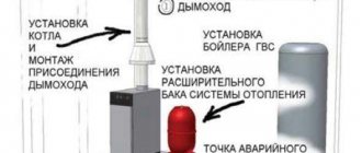
How to install a fire water supply
When laying internal fire water supply lines, fire safety requirements must be observed. In buildings, ERW is fastened by supporting it on the wall. You can support the water supply on the floor in basements, through sections of brackets installed along the entire length of the wall or partition.
Pipes can also be supported on hangers installed to the ceilings. When installing an ERW, if the pressure is more than 40 m, it is necessary to install a diaphragm. This is done to reduce excess pressure.
Crane maintenance
In addition to assessing the condition of the PC cabinet, specialists from the organization with which an agreement has been concluded for the provision of ERW maintenance services must start the water supply and evaluate the operation of the tap. Main control points:
- consumption;
- pressure;
- pressure.
Water loss tests, which show actual water consumption, are carried out at a temperature not lower than +5°C. Simultaneously with the flow rate, it is established that the pressure at the dictating valve corresponds to the standard or design values. This type of work involves the following sequence of actions:
- open the cabinet and disconnect the working hose from the PC valve;
- install a measuring device;
- connect a sleeve with a manual barrel to the device;
- reposition the sleeve, avoiding its kinks;
- direct the barrel into the receiving tank;
- two specialists take part in the test: one holds the barrel, the second opens the tap;
- record the pressure gauge data at the dictating valve;
- if the shut-off barrel is in operation, then close its valve;
- turn off the pump;
- fill out the test log;
- remove the measuring device;
- connect the working fire hose;
- seal the cabinet.
The pressure shown by the pressure gauge at the PC valve must be no less than the standard pressure according to the table.
Cost of installing a fire-fighting water supply system
The cost of installing a fire safety water supply system in a building depends on:
- The area of the object, its configuration.
- Requirements for the effectiveness of fire-fighting equipment.
- Project development needs.
- Consumption of materials (pipes, pumps, fire hydrants, hoses).
The final cost is calculated after the project has been agreed upon and the work plan has been approved.
Before drawing up an estimate, you can pre-calculate your budget using the prices provided.
| Name of works | Unit change | price, rub. |
| Installation of fire-fighting water supply (with dismantling of the old one) | m.p. | 1800 |
| Testing for water loss of VPPV | 1 PC | from 350 |
| Testing for water loss of LPPV | 1 fire hydrant | from 1100 |
| Rolling sleeves onto a new seam | sleeve | 150 |
| Checking the performance of booster pumps | PC | from 430 |
| Hydraulic testing of fire hoses | sleeve | from 110 |
| Replacing fire hydrant valves | tap | from 1050 |
| Replacement (relocation) of risers of the AFPV network | m.p. | from 505 |
| Repair of risers of the VPPV network | PC. | Negotiable |
| Tying half nuts to a fire hose | PC. | 110 |
| Installation of cabinets to accommodate a fire hose | PC. | from 210 |
| Dry pipe design | PC. | from 8 030 |
| Installation of dry pipe dia. 51/76 mm | m.p. | from 1 020 |
| Installation of dry pipe dia. 89/108 mm | m.p. | from 1 350 |
| Repair and replacement of fire hydrants | PG | from 4 050 |
PC health assessment
During maintenance, fire hydrants are tested for serviceability. This is done to prevent the shut-off valves from sticking. It is especially important to carry out this work on old water pipelines. During the inspection, the tightness of the valve shut-off element and the stem seal is also tested after several closing/opening cycles. If a diaphragm is installed between the outlet of the PC valve and the coupling-type connecting head, check its diameter according to the design data.
The test involves valves from all taps without exception. Typically, this work is combined with testing the system for water loss, while taking into account the maximum water flow in the water supply is not necessary. To check, use a plug head, which prevents water from flowing when the PC valve opens. The test protocol for testing the crane for serviceability is as follows:
- open the cabinet and disconnect the PR from the valve;
- using a caliper, measure the diameter of the diaphragm and enter the data in the journal;
- install the plug head;
- carry out three opening/closing cycles;
- check that there is no leakage through the rod seal;
- fill out the test log;
- close the valve and place a container under the drain to collect water;
- remove the plug head;
- attach PR;
- close the closet.
Tests are considered positive if there is free manual control of the valve shut-off element from the “open/close” position and there is no leakage after several cycles. It is also important that the diameter of the diaphragm matches the design data.
Testing of PC valves for serviceability is documented in acts and a separate protocol, which is attached to the general protocol for checking the ERW. The report must indicate the condition of the equipment (it can be opened freely manually or it is necessary to use additional technical means), describe the identified malfunctions and methods for eliminating them.
The test report is filled out according to a standard sample. It includes the name of the enterprise where the inspection was carried out, information about the organization that carried out the work, the time and date of testing of each PC, markings and type of equipment, test results, signatures of the specialists who participated in the inspection.
Installation locations
It is necessary to read out the entire list in order to understand the full range of demand and irreplaceability of PCs according to the table. 1 SP 10.13130.2020, which determines the required number of supplied trunks, water consumption per one compact stream of water, for irrigating each point in the space of protected objects, depending on the internal volume, number of floors, functional purpose of buildings:
- 12–25-story apartment buildings.
- Administrative institutions from 6 floors.
- Dormitories, public buildings, with the exception of administrative institutions, from 10 floors.
- A&B of production enterprises with a volume in the range of 5-25 thousand m3 and more.
- Theaters, cinema halls; club and other cultural and entertainment institutions - according to SP 118.13330.2012*.
On this topic ▼
Fire cabinets
Requirements, types, classification, placement standards
For production workshops, warehouse complexes, logistics centers with a height of no higher than 50 m, the requirements for the installation of ERW with PC are determined according to Table. 2 depending on the volume of the structure, the degree of fire resistance, and the fire and explosion hazard category.
In addition, according to SP 54.13330.2016, in residential buildings in each apartment it is necessary to install a faucet with a diameter of at least 15 mm for a hose/sleeve with a spray nozzle, which is actually a smaller copy of a standard PC, with the ability to supply water to any place in the apartment.
All these requirements apply to ERW systems at the design or reconstruction stage.
Important: this requirement in no way prevents, during major or current/seasonal repairs of water supply systems of buildings, from “bringing up” existing water supply systems, installing additional shut-off valves on pipelines with the installation of fire cabinets near them, in order to both bring the ERW into compliance with current standards and and reliably secure fire hazardous areas and areas.
Typically, in practice, thrifty owners are concerned about the safety of people and the safety of their own property; those who do not want to incur millions in losses from possible fires, be subject to administrative fines, and criminal prosecution, do so.
Where should taps be placed?
Fire Cabinet for PC
To safely store a PC, a special fire cabinet is used, which is least vulnerable to high temperatures. This fire safety element not only provides PC protection, but is also a signal element that immediately attracts attention. In addition to the PC itself, the cabinet can contain a fire extinguisher, other necessary equipment, as well as an alarm button.
What symbol is used to indicate a PC?
According to GOST 12.4.026 No. F02, the fire hydrant sign must have a hose and a flywheel. Background – red. Example:
An image of red or white letters “PK” in a frame is also allowed. Example:
What symbol is used to indicate a PC in the diagram?
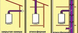
Diagrams or drawings use a circle divided into black and white halves by a straight line (pipeline). On the circle there is a flywheel in the shape of the letter “T”. Example:
PC Operation and Maintenance
The internal fire-fighting water supply network is usually created from welded steel assortment, less often it is installed from polypropylene plastic with a fire safety certificate.
Rules for PC content:
- all elements are connected;
- during the operation of fire hydrants should be taken 30 minutes;
- at least 1 m from heating devices (heat negatively affects the sleeve);
- the move is smooth, the unit is treated with synthetic lubricant;
- heated places;
- regular replacement of oil seal packings, gaskets, seals;
- prohibited: installation with the flywheel down;
- store items near the PC;
- litter the passages to the node;
- carry out redevelopment, repairs that impede access;
How to use the crane
On activating a PC there is: “Instructions for activating a PC.” Algorithm for one person:
- Break the seal, open the safety valve.
- Remove the fire hose - it is already connected and in standby mode with the barrel.
- Unwind the sleeve: holding the outer turn, throw it in the direction of the fireplace so that there are no twists. If there is a fire nearby, roll it along the free line of the room from the flame.
- Open the valve by turning the handwheel to the maximum mark.
- If there is a booster blower, after opening the lock, press its button.
- Take the fire hose with both hands and approach the fireplace. Adjust the jet to optimal compactness.
For glass, fibrous, bulk materials, wood, a spray jet is used. During the firefighting process, make sure that the path to evacuation and retreat is clear. {banner_downtext}
What pressure should be in the tap
Pressure according to PC standards:
- on average on the sleeve – 0.21 mPa (2.141 kgf/cm²);
- SP 10.13130 (Table 3) sets several dozen parameters for various diameters;
- hydrostatic pressure: about 0.45 – 0.60 MPa;
- the main regulatory document on ERW is SNiP 2.04.01. According to clause 6.7, there should be up to 45 m (water column) on the main line, and up to 90 m in a separate water supply system;
- The PC should not have more than 9 atm. (with a membrane to dampen pressure - up to 4 atm.). Calculation of the MPa reduction diaphragm is done using a nomogram (a 1985 sample is used);
- if the pressure is more than 0.45 MPa, install a separate water supply network;
- at a pressure of 40 m or more, a reducing diaphragm for the tap is installed;
Minimum operating pressure that the valve must withstand according to clause 1.4.1. GOST 12.2.037-78 – 10 kgf/cm² (1 mPa). According to NPB 154-2000 (clause 2.3, 5.5), tightness is ensured at a value of 1.25 MPa, the device should not be destroyed at 2 MPa. As a standard, the unit is designed for a working value of 1 – 1.60 mPa.
How often are taps checked?
Maintenance is carried out by specialized licensed enterprises, inspection is the responsibility of fire supervision. Maintenance and control are provided by the owner of the building or the person responsible for safety.
Checks:
- control of work, water return - spring and autumn (once every 6 months);
- rolling - once a year;
- inspection of the storage facility - once every six months;
- technical condition control (damage, equipment, markings) - every month.
PC water loss certificate: sample
The PC is tested for water loss using a hydrotester. The methodology is provided for by SNiP 2.04.01: the time of filling the container is measured when a large number of intake points are opened at the lowest water pressure. The dictating tap is the most remote (highly located) point, its indicators are of paramount importance.
The results are recorded in a water yield report. Displays: pressure value (statistical, dynamic), water flow at a certain number of opening/closing cycles.
Download: Certificate of inspection of the operability of the internal fire-fighting water supply network and the serviceability of fire hydrants.doc
Main characteristics
Fire hydrant modifications can be straight or angular. The corner model is more convenient to use if access to the pipe is limited. One fire hydrant connection is intended for connecting a water pipe, and the second is for connecting a fire hose.
The angle between the nozzles can be from 90° to 135°. The number of revolutions of the flywheel before the fire valve is fully opened depends on the diameter of the pipe and can be 4, 5 or 6. The valve must be fully open or closed. An intermediate position is not permitted.
For installation of a fire hydrant, a thread is provided, which can be internal and external (coupling and pin). Particular attention is paid to the quality of the thread. It should not have dents, undercuts or other defects .
The operating pressure of the valve is 1-1.6 MPa. It is designed to operate at water temperatures of +1…+50 °C. The diameter of the passage depends on the diameter of the water pipe to which the tap is connected. According to GOST standards, the nominal diameter is 40, 50 and 65 mm. The faucet flywheel is made red; when opening the valve, its rotation should be counterclockwise.